Hi BT,
The tonearm cable earth connects to the chassis of the VSPS/ultra which is further connected to the COM pad of the PCB, as per the connection diagram for the regular VSPS. That the battery charger does not have a third "earth" connection is not a concern here - you wouldn't connect it to the VSPS ground even if it did.
/R
Filter cap wiring.
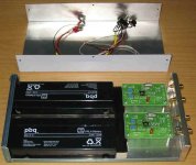
My phonoclone has two large filter caps in the box with the transformer and diodes. The smaller caps on the board should be decoupling, the lead in four feet long and 20 ga to give some resistance and inductance.
I do not have a scope, but do have a VOM that measures to 0.0 mv AC. This should tell if there is an ac component riding the rails.
Are there any downsides to running a wire from the cap ground to COM? Such as RFI.
The boards are finished, hate to remove them and replace the caps.
George
The filter caps in the power supply reduce the ripple and the charging currents in C8-11, so the shared ground connection will have less effect. I would leave the PCB as it is.
At least give it a few weeks to break in and for you to become familiar with the sound. If you start thinking that its a little soft, or slow - giving everything a vintage tint, like - then perhaps its time to start tweaking.
If your power supply voltages are over 18V, you might try adding 7815/1915s as pre-regulation. I'd do that before re-wiring the caps, at any rate.
The harmonics seen in the FFT spectrum are so low that the difference in the measured AC output voltage would most likely be below the measurement threshold. Your ear is a better detector: the ripple is a triangle wave, and sounds like buzzing. If you can clearly hear the buzz above the background hiss with the volume turned all the way up, then the harmonics are present. Dont forget you have to have your cartridge attached or a dummy load on the input before making any measurement.
I have 2 or 3 remaining sets of replacement 100uF/25 caps for those who bought phonoclone PCBs and want to do the mod. I will send these out free to the first people to email me to ask for them, but in return you are required to post your results here.
")
Since people have said the Phonoclone works better at lower voltages, and since I only have 15V DC on my power supply I plan to replace my 7812s with 7809s (or whatever I can find in that range) on the PCB and use the 7812s to pre-regulate the power supply. See how that flies.
Note that theres no need to go overboard on the preregulator. 20-40dB of ripple rejection is more than sufficient. Its temping to just add filter capacitance to get there, but this has its own set of problems. MOSFET series regulator? CRC filter? All kinds of options to play around if you want to.
/Richard
At least give it a few weeks to break in and for you to become familiar with the sound. If you start thinking that its a little soft, or slow - giving everything a vintage tint, like - then perhaps its time to start tweaking.
If your power supply voltages are over 18V, you might try adding 7815/1915s as pre-regulation. I'd do that before re-wiring the caps, at any rate.
The harmonics seen in the FFT spectrum are so low that the difference in the measured AC output voltage would most likely be below the measurement threshold. Your ear is a better detector: the ripple is a triangle wave, and sounds like buzzing. If you can clearly hear the buzz above the background hiss with the volume turned all the way up, then the harmonics are present. Dont forget you have to have your cartridge attached or a dummy load on the input before making any measurement.
I have 2 or 3 remaining sets of replacement 100uF/25 caps for those who bought phonoclone PCBs and want to do the mod. I will send these out free to the first people to email me to ask for them, but in return you are required to post your results here.
Since people have said the Phonoclone works better at lower voltages, and since I only have 15V DC on my power supply I plan to replace my 7812s with 7809s (or whatever I can find in that range) on the PCB and use the 7812s to pre-regulate the power supply. See how that flies.
Note that theres no need to go overboard on the preregulator. 20-40dB of ripple rejection is more than sufficient. Its temping to just add filter capacitance to get there, but this has its own set of problems. MOSFET series regulator? CRC filter? All kinds of options to play around if you want to.
/Richard
Lower Gain on Phonoclone
Hi all,
I promised to report back on my results when lowering the phonoclone gain for use with my Ortofon Kontrapunkt b cartridge, unfortunately just after making the mods I picked up an ear infection which left anything sounding like it was playing through a 1/2" tweeter with a torn dome!
I was actually quite worried for a while but mercifully my hearing is well on the way to recovery although not yet up to really critical listening.
I'm pleased to report however that dropping the gain setting resistors to about 1K did the job fine and at least through my left ear which is recovering faster than the right it now sounds truly wonderful and every bit a match for a $700 commercial unit I compared.
Thanks RJM for a great board and your help with the gain issue.
Best Regards,
Dave.
Novel idea
Read the idea about using another cartridge in the feedback loop. How would this work on the input of the phonoclone? I have another cartridge that has the cartilever broken off. It should match closer than the resistors already used.
Once mine new phonoclone is working properly I may try to evaluate. The two resistors I used are more usefull than my broken cartridge.
I did not follow the datasheets for the LM320/340 regs or the sage advice given by one here. The bypass caps on the output of the regs are 100 ufd ultra low impedance type. And guess what, the regs are acting up.
The unit had about 3 mv of ac on the output with no cartridge attached. I assumed this would go away once loaded with a 14 ohm load. Guessed wrong again.
One novel thing found. Disconnected the ground wire from the turntable to try and reduce the noise. Started picking up radio with the phonoclone. Not bad quality. First phono stage I have tried that did this. Usually grounding issues just give hum.
The noise I am getting is not hum. It is grittier. Got some 10 ufd ultra low impedance caps in the closet. Gunna install and some Onsemi 7812/7912 too. The specs show much less voltage noise than others of this type. Thanks for the tip!
George
Two posts, one phonoclone project looking good, the other obviously having some teething trouble.
Thus, some (more) comments about noise vis. the phonoclone:
HUM is the presence of sinusoidal line frequency (60Hz or 50Hz) AC on the output. It gets on the output most often by coupling of the magnetic fields produced by power transformers or the turntable motor into either the cartridge coils or some other part of the input stage. Moving magnets are more prone to this than moving coils, but inproperly connecting (or not connecting) the turntable ground wires can produce hum on a MC setup, too. I've never had any problem with hum in my setup. (Sheilded external power transformer, shielded wires, turntable grounds connected to the chassis of the phonoclone unit, which is itself connected to the phonoclone circuit ground.)
BUZZ is heard when some of the AC ripple riding on the DC power rails gets into the output. The ripple has the line frequency as its fundamental, but since its a triangle wave contains lots of higher order harmonics as well. It is not a pleasant sound. Fortunately the PSRR of the OP27 is high, and together with the ripple rejection of the voltage regulator this means only a tiny fraction of the unregulated DC ripple finds its way onto the output in normal circumstances. (Example: my stock phonoclone, gain 70dB, has an output ripple of about -72dB, or about 250uV rms. After the mod to change the ground layout, its reduced to 100uV- this together with over 1mV of broadband output noise, so its barely audible even with the volume turned up.) This is with only 100uF x4 of filter capacitance, and generic LM7812s. As hinted in the example, extra ripple can get into the output for all kinds of subtle and not-so-subtle reasons related to the grounding layout.
HISS/HUSH is most likely noise originating from the opamp itself, in normal operation. The OP27 is 3.2 nV/rtHz, and the Phonoclone is designed such that the circuit adds no significant noise above this. At 70dB gain, there will be about 1mV of broadband noise, mostly at frequencies below 100Hz. This is intrinsic to the design of the op-amp.
CHMR 101.3fm: Since the ripple rejection and PSRR both cease to be of much use at frequencies of 100kHz and above, high frequency noise (RFI/EMI) on the power supply cable or any of cables running into the box can be a problem in cases where significant amounts of it are present and no steps are taken to prevent it from getting to the phonoclone PCBs. I as said before, the phonoclone PCB has no defense against RFI, and moreover the bipolar-input OP27s are a little more prone to demodulating RF signals than FET types. So, yes, it will become a nice little FM radio if you give it a suitable antenna, as some of you have discovered. I've never had a problem with this myself.
Richard
sweet sound of ... nothing
To prove it could be done I put 1000uF of extra filter capacitance on each rail and re-measured the output noise.
There you are: the OP27 noise, and nothing but, up to 10 kHz. (Its looks clean up to 100k, as a matter of fact, but my measurement system has some noise spikes up there so it doesn't present well.)
And on the seventh day... zzzzzzzzzzzz.
/R
Attachments
Re: sweet sound of ... nothing
Am I correct in assuming that this is on the power supply rails before the regulators? Just to make sure.
rjm said:To prove it could be done I put 1000uF of extra filter capacitance on each rail and re-measured the output noise.
Am I correct in assuming that this is on the power supply rails before the regulators? Just to make sure.
Although adding the extra 1000uF of capacitance improved the measured noise performance, subjectively it completely killed the sound.
I dont know why. Have to do more tests first. The difference however was quite striking. The musical presentation was more controlled, solid, with better resolution of low level detail - but by the same token caught a serious case of "hi-end blah". Sounds good - but really, really boring. Like someone shaved all the sharp edges off. Lost all sense of rhythm.
So, like the gainclone, I have to recommend no additional capacitance in the power supply be included. How much filter capacitance (before the regs) I havent worked out yet. To my ears 100uF per regulator is fine, but up to 470uF would help to reduce the ripple harmonics at the output.
/R
Working Fine now
I replaced the 100 ufd ultra low impedance caps after the regs with 47 ufd Silmics. This got everything working properly.
The gain needs dialing in now. It is a little too high. Used a 1.1K resistor with a 14 ohm cartridge. It works fine, but may benefit a little by going with a 700 ohm of so to drop the gain on the first opamp.
It is very sensitive to input lead dressing. I have been playing with this for a while now. Hum and RFI come and go. Moving my shielded phono cables to get away from the input power cable solves it. Both are shielded, so this is a mystery.
Only got about 5 lps played so far. It is fast and clear. Very good dynamics.
This one has a bunch of capacitance before the regs. It maybe the 4 pole caps react differently than a 2 pole with chips. Distance may be a factor. The big caps are in with the transformer and diodes in another box 3 feet away.
The only weakness so far is a lack of warmth. This may be a new parts problem, hum or RFI issue, or just comparison to my usual phono stage. The Pearl with headamp is overly warm and ripe.
But very good results even with minimal burn in. Expect it to get even better with more playing.
Good job Richard!
George
Richard
I just built a second phono stage, designed by you: the VSPS, to play a little bit with different input-Z in conjuction with my DL103.
I will compare it with my phonoclone. It has a socket for the opamps to compare different opamps.
As I will be a member of the next European Triode Festival in beginning of december, it would be a nice idea to prepare a VSPS for the phono shootout. Imagine a IC-amp competing to a triode pre for example made by Steve Bench...
Could you please simulate or suggest a configuration for the Benz Ebony HO cartridge?
Here the technical part of the announcement from the shootout:
Kind regards
Franz
I just built a second phono stage, designed by you: the VSPS, to play a little bit with different input-Z in conjuction with my DL103.
I will compare it with my phonoclone. It has a socket for the opamps to compare different opamps.
As I will be a member of the next European Triode Festival in beginning of december, it would be a nice idea to prepare a VSPS for the phono shootout. Imagine a IC-amp competing to a triode pre for example made by Steve Bench...
Could you please simulate or suggest a configuration for the Benz Ebony HO cartridge?
Here the technical part of the announcement from the shootout:
the phono stages must comply with the following specs:
1. gain has to 40db or more (the follwing line stage will have an attenuator at the input so that all phono stages will be listened to at the same volume referenced to 0db@1kHz
2. the cartridge used for the shoot-out will be a Benz Ebony HO, known as "the best high-output moving coil of the world". it has an output voltage of 2.5 mV into 47k (3.45 cm/sec with JVC TRS07). the turntable will be an EMT 938 with a Fidelity Research FR64s tonearm.
3. the phono stages must accept a male 5 pin DIN connector for the incoming signal (pin 1=r+, 2=r-, 3=GND, 4=l+, 5=l-; numbering clockwise viewed from the soldering side). we will provide an adapter for RCA-DIN, but you might not want to compromise the sound of your phono stage with this adapter... important: the wiring of the tonearm is balanced and ground-free - pls take this into consideration when you build the phono stage and--very important!--you *must* provide a ground on your phono stage (banana or spade lug)
4. the phono stages must run either on 230 vac/50hz or on batteries. we will not provide a line conditioner, step-up x.former for 115vac or similar - if your phono stage needs clean juice, make sure the power supply filters out mud and crud.
5. the output of the phono stages must be available on either RCA, CAMAC or XLR, signal can be balanced or unbalanced
6. there will be an attenuator unit between the phono stages and the following line stage. this attenuator with z in=10k ohms i.e. the phono stages must be able to drive this load. the input of the line stage is rc-coupled. (subject to change, but the 10k more or less stands.)
7. if your phono stage hums - tough luck...
Kind regards
Franz
Imagine a IC-amp competing to a triode pre for example made by Steve Bench...
OUch!
If you are dead set on doing this, however, there are no special modications required. The standard VSPS, 47k input resistance, 40dB gain, and the usual ground connections, will suffice.
As you know, the circuit lives or dies on the power supply... with some additional tuning possible though parts selection in the circuit itself.
I have plenty of ideas ... feel free to email me and discuss.
Richard
Playing happily away.
Finally tried lowering the gain of the first stage to 45 or so. This is using a 618 ohm resistor and the listed 14 ohm impedance of the Denon DL-103R.
Used a 150 pf cap across pins 2 and 3. This was discussed early in this thread. There is a desolate area to my west with all the Houston TV transmission towers. It is only maybe 8 miles as the buzzard flies.
Never had this problem with a couple of transformer boosted tube phonos and the current all solid state unit. I think I know why.
My knowledge of opamps is minimal. So it may be a trick coming from using the inverting input.
But looking at this circuit it looks to have infinate impedance. Not zero. What is zero is the loading. The high input impedance sets you up for hum and rfi issues.
Soundwise, this is very good. Still have a little hum to chase. But very live and dynamic presentation.
Walking around the room causes the level of hum to go up and down. This should be fixable. The unit appears to be very quiet on its own.
Now to get another 20 hours or so of playing on it.
George
- Home
- Source & Line
- Analogue Source
- The Phonoclone and VSPS PCB Help Desk