My (idiotic) mistake!
Richard,
I took the voltage regulators out and still had the problem. Measured the voltages on my lambda supply and Bingo: the +/- rails were wildly unequal. Turns out my lambda LA-200 supply isn’t a double rail supply at all! It has a “ground” binding post between the positive and negative posts, which made me think it was a split supply but it’s not (red face).
Ordering parts for a proper supply.
Sorry for wasting everybody’s time!
Dint
Hi,
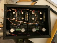
While our workshop access in the office is restricted I thought of just finishing the Emereld without a bigger case (and not the best looking..)...so:
My V++/-- is 16.5ish but when I try to match Ref with V+- one side has equal voltages with V+- = 12.97V and the other with V+- = 12.65V
Any idea why is that?!
Thanks
Attachments
That's normal because the regulated output takes the diode drop V_be of the transistors Q7 and Q8 as its reference. You'll have some variation in the transistors, so the output varies in proportion.
I know it gets on people's nerves because everyone likes perfection, but a few hundred mV on the rails isn't going to change anything and is nothing to worry about.
[If I'd cared enough, I could have made it that V+ and V- were independently adjustable by simply adding a second potentiometer. It's one of those cases where "close enough" is fine, so I didn't bother.]
Last edited:
thanks for the reply!!
So no imbalance in the audio signal due to this 0.5V diff between channels?!
One other thing I realised is that the power supply (all based on BOM, VPM24-1040 with White and Violet for 240V and Yellow/Orange - Black/DeepRed on the two rectifiers) is 'leaking' 0.5V on the V++ side when OFF. Im a complete newbie when it comes to mains power supplies...
Is there an obvious mistake?!
- no, no imbalance, the enormous DC feedback over the op amps takes care of that.
- if there is no power applied to the transformer, there can be no voltages ... but sometime residual polarization in the electrolytic caps can cause some voltage to be measured even after the power as been off for a minute or two. It's not "leakage" as I understand it, unless I have completely miss-read what you observe.
- if there is no power applied to the transformer, there can be no voltages ... but sometime residual polarization in the electrolytic caps can cause some voltage to be measured even after the power as been off for a minute or two. It's not "leakage" as I understand it, unless I have completely miss-read what you observe.
- no, no imbalance, the enormous DC feedback over the op amps takes care of that.
- if there is no power applied to the transformer, there can be no voltages ... but sometime residual polarization in the electrolytic caps can cause some voltage to be measured even after the power as been off for a minute or two. It's not "leakage" as I understand it, unless I have completely miss-read what you observe.
I think I have connected the fuse/on-off in a wrong way as with the switch OFF there is a big of voltage on the ++ side. Am I looping to ground or something? If I unplug the power cable complexity of course I have to voltage as you said.
Distortion Persists...
Hello,
Dint here. I built the suggested power supply but still hear a staticky/tearing distortion in both channels (as in attatched mp4 file). The distortion is even more pronounced with CD sources run through a inverse RIAA filter, but pure tones (from Stereophile Test CD) sound fine.
I can’t imagine what could effect both channels in this simple and symmetrical circuit other than a fried OPAMP. Unfortunately, I soldered my MUSES 01 directly into the circuit board. I did accidentally power it with 16VDC when I bypassed the onboard regulators and used an external regulated supply. Do you think that could be the problem?
I would be grateful for any suggestions before I try to desolder the MUSES and replace it with an OPA2134.
Thanks again,
Dint
Attachments
Eureka!
Richard,
I think that must be it. I have the stereo VSPS and R2 is 680 ohms, but my cartridge - an ancient Pickering 38 - may have an output of up to three times higher than normal (15mV, according to this webpage: Doctorjohn Cheaptubeaudio: Audio Reviews and More: Shure M44-7 Stanton Pickering 380 Empire EDR.9 Harman Kardon Citation I).
Thank you! And what value of R2 would you suggest?
Dint
trichotillomania
Argh! Rush ordered and installed some 2.2K resistors, and while the volume is reduced the distortion is, if anything, worse. I’ve attached a file showing what it sounds like via CD/RIAA inverter. Again both channels.
What should I do? Replace IC? Start over?
Thanks, Dint
Argh! Rush ordered and installed some 2.2K resistors, and while the volume is reduced the distortion is, if anything, worse. I’ve attached a file showing what it sounds like via CD/RIAA inverter. Again both channels.
What should I do? Replace IC? Start over?
Thanks, Dint
Attachments
Another possible problem
I drilled my VSPS board to accommodate 16 gauge stranded wire - for both signal and power connections. Does the board depend on through-hole plating to connect traces on opposite sides of the board?
I can’t imagine that I could have damaged signal traces equivalently in this way, but maybe I screwed up the shared power?
I will order a fresh board and transfer everything to it - without drilling of course!
Dint
VSPS Voltage regulators
VSPS PCB on order as a birthday present to myself, looking forward to the project!
Quick question that I'm hoping someone can help me with - apologies if it's already been covered, I did have a good look but couldn't find an answer. I happen to have some 7815/7915 voltage regulators kicking around, would anybody anticipate any issues running an NE5532 at 15V? And does anybody have any comments regarding whether or not this may be "less optimum" than the BOM 12V, and if so, why?
- I find the op amps sound warmer at 9-12 V
- 15 V results in a tighter, cleaner sound so if that's what you are aiming for by all means
- If you use 15 V regulators, you'll need 15 VAC secondaries on the transformer
- The filter capacitor voltage rating should be increased from 25 V to 35 V
Amazed...
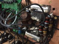
After many problems, my hot-rodded VSPS is now delivering amazing sound in my (mono) system. Very musical and transparent - can hear deep into good recordings - and very emotionally engaging. The OPAMP is a Muses01 (FET). Almost all resistors are Allen Bradley’s, the electrolytic are Audio Note Kaisai models liberated from their aluminum cans and wrapped in Japanese paper casings. The RIAA caps and electrolytic bypass caps are glass dialectic, and the coupling cap is the amazing V-cap ODAM.
The VSPS is fed by an ancient Pickering 380 “Chicken Head” cartridge running at very high tracking force (about 4g). This is mounted on one of Jurijs Redins’ 12” wooden EMT banana replica tonearms (beautiful and inexpensive) which rests, in turn, on an external arm-pod from TemaAudio of New Zealand. The turntable is a Denon VL12 prime “DJ” model.
The VSPS feeds a Stereo Coffee LDR preamp - which in turn feeds a single (highly modded) Brook 12a push-pull 2A3 amp driving stacked Spendor BC-1 speakers. All wiring except the phono cable is Duelund 16 gauge (need to make a Duelund phono cable!).
The preamp is wonderful, and almost certainly my last. Thank you Richard, both for your work, and for your patient help!
Dint
Attachments
Thanks Richard, duly noted, interested to learn that it makes such a perceivable difference - clearly, the whole power supply/voltage regulation side of the VSPS is pivotal to how the whole thing will sound. I'll keep things strictly BOM for the time being, I may experiment later with other options. Now let's see if I can get everything else ordered in before the PCB arrives!
- Home
- Source & Line
- Analogue Source
- The Phonoclone and VSPS PCB Help Desk