Ah, right, what changed? And which other designs work better with your phono stages?
I've punted on designing my own power amp, I'm still using the Treasure 0347.
Though the temptation to slap some big headsinks on the Sapphire 4 and connect it to speakers is strong, truth be told the 0347 isn't so far off exactly that.
OpAmps for the VSPS 200/400.
The OPA 134 works perfectly in these circuits. The Analog Device's AD797 however does'nt - too my surprise I might add. The sound being highly distorted and with no signal "motorboating" is clearly audible.
Any suggestions would be appreciated as the AD's are rather costly.
The AD797 is not suitable as the front end of a MM phono stage.
Please search this thread for "AD797" for the details, paying particular attention to vulejov's comments. As he notes, the AD797 can be used by reconfiguring the VSPS as an MC phono stage, making appropriate modifications.
I've punted on designing my own power amp, I'm still using the Treasure 0347.
Though the temptation to slap some big headsinks on the Sapphire 4 and connect it to speakers is strong, truth be told the 0347 isn't so far off exactly that.
Interesting, I wasn't aware of the DIY kits from 47 labs. As for me, my audiosector GC works pretty great with my Markaudio speakers and are clearly a cut above the ss receivers/TPA3116/TA2024 amps I've used with them before.
Richard, they arrived !!!!!
Very good quality and appearance. Thanks for the "little gift".
Now to assemble it. I will try to do it with the best quality components I can get.
Greetings. Then I will comment. For now I'm still with VSPS 300.
Very good quality and appearance. Thanks for the "little gift".
Now to assemble it. I will try to do it with the best quality components I can get.
Greetings. Then I will comment. For now I'm still with VSPS 300.
An externally hosted image should be here but it was not working when we last tested it.
Richard, I'm making the list of materials to assemble the VSPS400.
I have to buy them on eBay, since quality components are not available in Uruguay.
The idea is to use resistors Dale metal film 1%, capacitors silver mica Cornell Dubilier 1n 1%, electrolytic Nichicon KZ MUSE
I ask, does R5 have to be a carbon resistor?
Greetings, Josè.
I have to buy them on eBay, since quality components are not available in Uruguay.
The idea is to use resistors Dale metal film 1%, capacitors silver mica Cornell Dubilier 1n 1%, electrolytic Nichicon KZ MUSE
I ask, does R5 have to be a carbon resistor?
Greetings, Josè.
<snip>
Finally, I recently discovered Triad VPM medical transformers with screen and shield are available at digikey and similar outlets. So today, I would change my recommendation from "bigger" to "better" and suggest everyone goes with the VPM if they want to upgrade their power supply.
I know its going back over a year, but I have a question about the Triad Transformers. The datasheet states
SourcePrimary and secondary windings are designed to be connected in series or parallel. Windings are not intended to be used independently.
As the power supply rectification does not directly connect the windings, does this mean that its not suitable?
I'm using a PC3 for now, maybe a PC4 later on.
@ALPUY No, carbon composition is recommended for R5 (a quirk of mine), but any type of resistor can be used.
@Mr Onion The secondaries are always tied together and through just ~1.2V diode drop of the rectifiers. Though now that you bring it up, with my recommended 2-bridge connection scheme the side of the winding connected to COM does flip back and forth every cycle. I don't think it makes a big difference to performance if you connect as I have shown. But I am open to discussion on it.
@Mr Onion The secondaries are always tied together and through just ~1.2V diode drop of the rectifiers. Though now that you bring it up, with my recommended 2-bridge connection scheme the side of the winding connected to COM does flip back and forth every cycle. I don't think it makes a big difference to performance if you connect as I have shown. But I am open to discussion on it.
Last edited:
<snip>
@Mr Onion The secondaries are always tied together and through just ~1.2V diode drop of the rectifiers. Though now that you bring it up, with my recommended 2-bridge connection scheme the side of the winding connected to COM does flip back and forth every cycle. I don't think it makes a big difference to performance if you connect as I have shown. But I am open to discussion on it.
Thanks Richard, it was more of less what I was thinking but I always like to check first
Hi. Regarding the power source. I have a 50-watt toroidal with double secondaries of 12 volts alternating. Rectified would be in 16,97 volts continuous. Subtracting the fall that produces the rectifier diode would be close to +16 volts
Using the S-Reg, how do I calculate the voltage at the output of the reg ?. I see in the circuit you need + - 18 volts to deliver + - 12 volts.
I'm interested in remaining in + - 12 volts because I think it gives more dynamics to the circuit compared to the + - 10 volts that the VSPS 300 had.
If I use ultra fast diodes, Schottky diodes like BYV27-150 improve the performance of the source ?. I decrease the voltage drop when rectifying the alternating voltage, giving higher final voltage ?.
These are questions from a hobbyist with superficial knowledge about the subject.
regards
re. the S-Reg (part no. refer to the VSPS400, but the discussion to the Phonoclone 4 also)
R15,16 is increased to increase the output voltage. The 10k BOM value gives about 12 V. Reducing it to 6.8k gives 9 V output. I haven't worked out the exact response, but it's basically linear, so,
resistance value = ( [desired output voltage, volts] / 0.62 -1 ] / 2) kohms
As long as there is about 2-3 V of dropout voltage the reg works fine, so you want at least about 15 V on V++ for 12 V output.
Short story, use 10k if you want to run at 12 V.
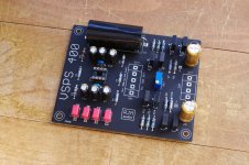
VSPS400
So this happened.
I'm using the help desk to get help with my own circuit. haha.
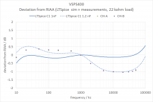
Instead of the nice flat simulated RIAA response, I measure what seems like the response when C1 is 1.2 nF instead of the 1 nF used. There is 200 pF of "extra" (parasitic?) effective capacitance across the 768k resistor R4.
No, it's not caused by parasitic capacitance to COM. It can only be induced by capacitance bridging over the resistor, as C1 does. And yes, the parts values are correct.
I would expect a little bit of additional capacitance from the resistor itself, but as far as I can determine that might be an order of magnitude smaller, 10 pF or less.
Any thoughts as to where the mysterious 200 pF comes from?
The fix is relatively painless - just reduce C1 by 200 pF, to 800 pF or so. I suggest replacing the 1nF cap with 330 pF and 470 pF in parallel.
So this happened.
I'm using the help desk to get help with my own circuit. haha.
Instead of the nice flat simulated RIAA response, I measure what seems like the response when C1 is 1.2 nF instead of the 1 nF used. There is 200 pF of "extra" (parasitic?) effective capacitance across the 768k resistor R4.
No, it's not caused by parasitic capacitance to COM. It can only be induced by capacitance bridging over the resistor, as C1 does. And yes, the parts values are correct.
I would expect a little bit of additional capacitance from the resistor itself, but as far as I can determine that might be an order of magnitude smaller, 10 pF or less.
Any thoughts as to where the mysterious 200 pF comes from?
The fix is relatively painless - just reduce C1 by 200 pF, to 800 pF or so. I suggest replacing the 1nF cap with 330 pF and 470 pF in parallel.
Attachments
If I did not understand English, you should substitute C1 (1nF) for 800 pF.
My idea was to assemble it with Cornell Dubilier 1% silver mica capacitors.
But if I have to do parallel 330 and 470 pF I no longer know if it is possible.
I can use Wima but I do not know if it should be MKP; MKT or FKT.
What is the opinion of the capacitors Mylar film (I find them very cheap in comparison to the others).
Since I'm going to spend money on components, I want to get the best result.
I have not made the purchase of components yet.
Thanks for warning in time.
Regards, Jose.
Hi Jose,
Yes, the solution is to replace C1 with 800 pF. It's only a stopgap solution though, because I do not know why this correction is needed in the first place. In previous builds the measured and simulated responses have lined up - and I can see no reason they didn't this time.
Please wait a few days while I make a detailed investigation. I may have made a mistake in the measurement setup, and there are several other things I need to check.
Note that -1 dB at 10 kHz is still a perfectly nice-sounding phono stage. Many people might even prefer it to the ideal RIAA curve as being a somewhat darker sound - if they could tell the difference, which I doubt anyone could except in direct comparison That's not to excuse the equalization error, I just want to point out that you can go ahead and use your VSPS400 as it is now and worry about the fine correction later. It's a relatively small thing.
VSPS400
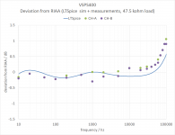
Forget I ever posted those earlier measurements.
&%$#% 10x scope probes. Screw me over every time.
The results below were obtained with regular RG58/U coax cable. The output load was 47.5 kohms.
The hp 3325B function generator and Tektronix TBS1052B scope were checked for accuracy in pass-though within the measured frequency range 10-100k.
The VSPS400 1kHz simulated gain is 40.8 dB. Measured results was 41.0,41.3 dB. The absolute measurement error is 0.3 dB, the relative error +/- 0.1 dB.
Good, no?
Attachments
Last edited:
- Home
- Source & Line
- Analogue Source
- The Phonoclone and VSPS PCB Help Desk