Hi there!
I have a simple question:
What is the hole size on the VSPS pcb for the resistors? I plan to use component sockets for some of the resistors so swapping them would be done without soldering if needed.
Apologizes if this has been answered somewhere...
Thanks,
Mikko
I have a simple question:
What is the hole size on the VSPS pcb for the resistors? I plan to use component sockets for some of the resistors so swapping them would be done without soldering if needed.
Apologizes if this has been answered somewhere...
Thanks,
Mikko
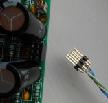
this is the solution i came up with for swapping out different value resistors.
An externally hosted image should be here but it was not working when we last tested it.
An externally hosted image should be here but it was not working when we last tested it.
An externally hosted image should be here but it was not working when we last tested it.
Nice.
I plan to use that kind of terminal: Barrette tulipe - 1x40 points droite - Barrettes tulipe.
Your solution looks smarter. What's the name of these terminals?
I plan to use that kind of terminal: Barrette tulipe - 1x40 points droite - Barrettes tulipe.
Your solution looks smarter. What's the name of these terminals?
That's what I have been using. Works fine.Nice.
I plan to use that kind of terminal: Barrette tulipe - 1x40 points droite - Barrettes tulipe.
Your solution looks smarter. What's the name of these terminals?
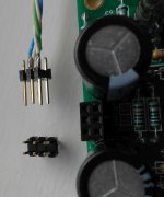
just dug out the pin strips. the ones i used were Harwin M20
Mouser part#
5 way wire housing, 855-M20-1060500
40 way breakable pin strips, 855-M20-9734045
Crimp terminals, 855-M20-1180042
when using the pin strips you can remove 3 pins in between with pliers (they slide out easily) to keep things square.
Mouser part#
5 way wire housing, 855-M20-1060500
40 way breakable pin strips, 855-M20-9734045
Crimp terminals, 855-M20-1180042
when using the pin strips you can remove 3 pins in between with pliers (they slide out easily) to keep things square.
An externally hosted image should be here but it was not working when we last tested it.
Last edited:
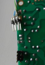
I leave the extra pins in place and add extra receptacles to the plug.
That gives a stronger mechanical grip for plug to socket.
I also pair off two pins and two receptacles so that it has double the contact points for each signal.
An example was for the NX PCB.
The three pins @ 0.1" were standard. Two Signal Return and one Signal Hot.
I solder on a 6pin DIP Header, so that the PCB now had 4 Signal return receptacles amd two Signal Hot. The 6pins are on a grid 0.2" wide by 0.1" deep.
I used a star quad cable to a 6pin DIP plug. The two signal Hot wires went to the two middle pins.
The two Signal Return went to the two diametrically opposite Return pins. That gave my connection 4 sliding contact points for the Hot and 4 sliding contact points for the Return. And 4 more sliding contacts to increase the mechanical grip.
Last edited:
I leave the extra pins in place and add extra receptacles to the plug.
That gives a stronger mechanical grip for plug to socket.
I also pair off two pins and two receptacles so that it has double the contact points for each signal.
An example was for the NX PCB.
The three pins @ 0.1" were standard. Two Signal Return and one Signal Hot.
I solder on a 6pin DIP Header, so that the PCB now had 4 Signal return receptacles amd two Signal Hot. The 6pins are on a grid 0.2" wide by 0.1" deep.
I used a star quad cable to a 6pin DIP plug. The two signal Hot wires went to the two middle pins.
The two Signal Return went to the two diametrically opposite Return pins. That gave my connection 4 sliding contact points for the Hot and 4 sliding contact points for the Return. And 4 more sliding contacts to increase the mechanical grip.
Not following this. Can you post some pictures?
That's what I have been using. Works fine.
Maximum diameter is 0.56mm so I'm wondering if the 0.6mm resistor leads will fit easily...
just dug out the pin strips. the ones i used were Harwin M20
Mouser part#
5 way wire housing, 855-M20-1060500
40 way breakable pin strips, 855-M20-9734045
Crimp terminals, 855-M20-1180042
when using the pin strips you can remove 3 pins in between with pliers (they slide out easily) to keep things square.
An externally hosted image should be here but it was not working when we last tested it.
Thank you!
")
one other thing i done was to scribe the resistor value onto the housing so i knew what was what without resorting to a DMM or colour bands.
other ways i have seen people do it is to have phono or jack sockets wired to the resistor holes on the boards then onto the back of the case and use 'dummy' plugs with the resistor soldered between hot/cold pins. but i think that might increase the resistance i dont know. might get a tad expensive as well.
other ways i have seen people do it is to have phono or jack sockets wired to the resistor holes on the boards then onto the back of the case and use 'dummy' plugs with the resistor soldered between hot/cold pins. but i think that might increase the resistance i dont know. might get a tad expensive as well.
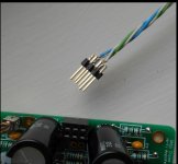
here is the 6pin DIP plug and socket I used to connect a 2pin Signal to the NX amplifier PCB.
The 4 outer most pins are the Signal Return. The two middle pins are the Signal Hot.
The plug has the two white Signal Returns attached to the diametrically opposed outer pins. The two grn/blu Signal Hot of the star quad are attached to the two middle pins of the plug. This sort of maintains the fields of the quad through the pins to the socket.
Attachments


Maximum diameter is 0.56mm so I'm wondering if the 0.6mm resistor leads will fit easily...
Hi,
I was thinking this too and decided to try. I had one 2x20 socket with 0,56mm holes and it seems to work just fine. One just needs to use slight force to push the resistor lead in its place to make sure it is secured. Resistor didn't drop even if I turned the socket upside down.
So, this is what I am going for.
Cheers,
M
- Home
- Source & Line
- Analogue Source
- The Phonoclone and VSPS PCB Help Desk