hi guys
i was looking into how to build a cheap but good quaility brushless motor for my prototype DIY turntables ...and i found this
http://www.audioorigami.co.uk/FloppyProject/FloppyDIYMotor.htm
for only a few quid make a excellent project ...and total time to convert is a few hours
cant be bad can it?
any questions feel free to ask
best wishes
j7

hi m8ty
Power from these floppy drive motors varies from unit to unit ...all seem to be able to pull inner and outer platters of standard weights ...e.g. linn / thorns etc
You can hold the motor and stop it dead...the unit has built in stall control...reconnect power and it’s on again
The main feature of concept here is that the power supply to drive the motor is a cell phone battery.... you have to spend a lot of cash to better a battery supply
Plus the motor only uses a tiny current...they are very efficient
And new type mobiles use lithium polymer and lithium ion batteries.... your phone charger can power your turntable
basic pictures are on my web site ....more to follow this week
best wishes
j7
This is a project I´ve been waiting for! So damn cool (and cheap)!
Please finish the guide soon, Audioorigami, please
I have a plinth, a Mayware formula4 mk3, Linn LP12 subplatter w/ bearing + subchassis and an Originlive platter.
I am just missing a motor and control circuitry.
I tried a couple of dc motors with LM317T, but the speed kept wandering ( so I thought "sod it" and put the almost finished TT away a couple of months ago).
hi tom
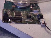
the new type floppys are what i have gone for ...simply coss they very easy to find
infact the old 5inch floppys are much better because they used bigger stronger motors...its the same wireing to make them work ...and slightly more ma to drive them ...so yes the 5 inch type are even more perfect....again every manufacter has made its own types ...so half the fun is opening the unit to see
these units are all negatively - triggered....
pins 12 and 16 are conected to the - of the battery pins 1-33 are all - as well....you cant do the unit any harm with a 4 or 5volt (mobile phone )battery...so dont be scared to try out things
the 12volt circuit is not needed in our use ...only the 5 volt side
12v (yellow) and 5v (red)...although a 12v battery could be used if you wanted with a drop down 5v regulator
i will have some time to photo my test unit with vary speed and wireing ill post tonight
so get out and grab some junk out your bin
best wishes
j7
]


Konnichiwa,
Very nice. I have quite a few large & heavy old SCSI Hard Disks probably 5000 RPM. I wonder if we could convert these into a turntable drive. Bearings must be marvelous (given the tolerance) and the heavy disk stack would make a great flywheel.
Maybe use two, one as motor and with a reduction belt with the spindle part of the disk pack used as the pulley to a second disk stack where you simply wind a strip of metal around some of the disks to make the larger pulley and to use as flywheel.
Leave on the second diskstack again a single disk pair open and use the spindle again as pulley to the platter.
The spindles on my disks are < 1" and the Disks outsides around 5", so we get from a 12" platter a reduction of around 1:12 or around 400RPM and another 1:5 reduction to give us the need for 2000RPM on the actual motor.
Sayonara
AudioOrigami said:i was looking into how to build a cheap but good quaility brushless motor for my prototype DIY turntables ...and i found this
http://www.audioorigami.co.uk/FloppyProject/FloppyDIYMotor.htm
Very nice. I have quite a few large & heavy old SCSI Hard Disks probably 5000 RPM. I wonder if we could convert these into a turntable drive. Bearings must be marvelous (given the tolerance) and the heavy disk stack would make a great flywheel.
Maybe use two, one as motor and with a reduction belt with the spindle part of the disk pack used as the pulley to a second disk stack where you simply wind a strip of metal around some of the disks to make the larger pulley and to use as flywheel.
Leave on the second diskstack again a single disk pair open and use the spindle again as pulley to the platter.
The spindles on my disks are < 1" and the Disks outsides around 5", so we get from a 12" platter a reduction of around 1:12 or around 400RPM and another 1:5 reduction to give us the need for 2000RPM on the actual motor.
Sayonara
Very nice. I have quite a few large & heavy old SCSI Hard Disks probably 5000 RPM. I wonder if we could convert these into a turntable drive. Bearings must be marvelous (given the tolerance) and the heavy disk stack would make a great flywheel.
Yes, you would think the bearings would be good. But why are they so damn noisy? Noise = vibration, no?
Spindle motors are way cool.
I pulled apart a DVD drive, and found the same kind of motor, except it has 9 poles, where yours has 12. I think they are all 3 phase motors.
I did a little research to find out how they work, and it's pure genius. You'll notice three tiny hall effect sensors near the stator poles. These sense the magnetic field of the ring magnet in the rotor. The signal from the hall effect sensors is amplified and fed back into the stator magnets. This provides precise control of the phase and current with respect to the actual position of the rotor. It's brilliantly simple and elegant.
The control chips have a servo input, so it should be possible to phase lock the motor to a crystal oscillator if you want very accurate speed.
I also did some research about the ring magnets, and it seems they may be magnetized with multiple north/south poles around the circumference, e.g. 3 pairs for a 3 phase motor. I was unable to determine if my rotor was magnetized like this though.
What's odd, is that you cannot feel any poles as you rotate the rotor by hand. Yet, it's a permanent magnet motor.
- Status
- This old topic is closed. If you want to reopen this topic, contact a moderator using the "Report Post" button.
- Home
- Source & Line
- Analogue Source
- New EASY DIY brushless motor