I am designing an AC power supply for my turntable (VPI HW-19), something along the lines of the VPI 'electronic flywheel'. The goal is an accurate, 60/81.8 Hz (33/45 RPM) 120 VAC sine wave generator, approx .5 amp capacity.
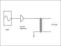
What I have in mind is: accurate low level adjustable oscillator, into a class B amp module, output of which would go to a step up transformer.
I realize that this may not be the most refined approach, but I am not an electronics desigh specialist, I am more of a systems person.
I would appreciate any comments from the group.
Refer to the attached file for a block diagram.
Attachments
That'll work.
I built one similar about 10 years ago, and it worked fine. Here's one I have on file, but I don't remember where I got it from, so I can't credit it. It's also about 250k, so I can't directly post it here. It's for a Garrard 401.
The one I linked uses an oscillator based around the 741 opamp, whereas mine used the xr8038 oscillator chip as I had some lying around. I think it might also be more temp and voltage stable. Mine drove a 24V Papst motor, so I used an ILP 20W integrated amp module, and as it was single speed, I used extra opamps to lower the xr3038 distortion further.
My Rock TT has a power supply that's also similar, so it's a doable idea.
<a href="http://members.optusnet.com.au/~xx308/401psu.jpg">TT psu</a>
<a href="http://www.amnesiak.com/ee478/xr8038a.pdf">XR8038 datasheet in pdf</a>
There's no reason why you couldn't also do it with an eprom blown with a wavetable clocked out through a dac. It would be a bit more complicated, and requires access to an eprom programmer.
Did you know that there was an article by Gary Galo that appeared in Audio Amateur around 1988 dealing with a power supply/speed control for AC motors?
I built it about eight years ago, and it made a world of difference in my vinyl playback. I suggest you check it out before re-inventing the wheel.")
I built it about eight years ago, and it made a world of difference in my vinyl playback. I suggest you check it out before re-inventing the wheel.
Electro said:
Hi,
these are not for AC motors (magic words: motor with brushes), it is a phase cutting device giving only a fraction of full phase of the AC power to the motor.
What you need is a real "motor controller" for 3 phase motors.
regards,
Hartmut
That kit is a start.
With all AC motors you can't get very accurate. For an accurate of 33 RPM or 45 RPM. gilid, could use a stepper motor. They are much more accurate and he or she can use it on any outlet or car. Though if gilid will be doing some effects with the turntable. He or she can not do it with stepper motors because of they have a built in breaking system.
With all AC motors you can't get very accurate. For an accurate of 33 RPM or 45 RPM. gilid, could use a stepper motor. They are much more accurate and he or she can use it on any outlet or car. Though if gilid will be doing some effects with the turntable. He or she can not do it with stepper motors because of they have a built in breaking system.
Electro said:That kit is a start.
With all AC motors you can't get very accurate. For an accurate of 33 RPM or 45 RPM. gilid, could use a stepper motor. They are much more accurate and he or she can use it on any outlet or car. Though if gilid will be doing some effects with the turntable. He or she can not do it with stepper motors because of they have a built in breaking system.
I fail to see why AC motors are inherently inaccurate. A synchronous motor (like the one in my TT) will lock on (ie, synchonize; hence the name) to the AC power waveform, as long the frequency is within its design limits. The only downside I see is a relatively large moment of interia, compared to a DC motor of equivalent output.
I would not use a stepper motor because of the inherent cogging effect. Yes, that can be minimized by proper waveform shaping, but that requires a very complex controller.
I think I will stick to my original concept, as layed out in my starting post. Which brings to mind another question - is this concept scaleable? Could it be taken from a low powered unit (25 W or so) to a high power (>500W), suitable for providing AC power to a preamp or amplifier, a la Power Station?
Everything I could find on synchronous motors indicate that dc is used to excite the rotor into movement. When the rotor reaches speed it switches over to ac and then as you said maintains its speed. There are actually two things that determine a motors synchronous speed:
1) the number of poles
2) the frequency of the applied voltage
Be careful how many poles the motor has that you buy. I would take a look at the circuit that drives the motor in your turntable and see how they did it first. Good luck
1) the number of poles
2) the frequency of the applied voltage
Be careful how many poles the motor has that you buy. I would take a look at the circuit that drives the motor in your turntable and see how they did it first. Good luck
The system in my TT is relatively crude - a syncronous AC motor driven directly from the AC mains. There is no control circuit whatsoever.
My problem is that the TT was purchased in N. America, and the TT is designed to run at 33 RPM with a 60 Hz AC power input. I now live in a 50 Hz country, and I miss my TT.
So, my options are several - I could machine a new pulley, with slightly larger diameters to compensate, or I could build a synthesised power supply, which is what I will most likely do. That should not only allow me to operate my TT, but it should yield an overall improvement.
I figured that if you had more than one speed they had to have something else in there. You may do a search on frequency drives or pulse width modulation. These are the principles behind the speed controlling of AC motors. You also might look for a motor upgrade for your unit. It was probably sold in Europe as well. There are some links in the analog sections buried in the posts to some sites in Europe. A cheap idea to experiment with is a capacitor. Perhaps you could modify the frequency with the right size. Good luck
AC motors
You folks are all trying to re-invent the wheel when it is not necessary!
The gentleman from France need only research the aforementioned Audio Amateur article by Gary Galo. The AC power supply/speed control is an easy project to build, and can easily be adapted to output 50 or 60Hz as required (also higher frequencies for 45 and 78RPM as well--it's all explained in the article). It can also run on 120 or 240VAC mains.
An AC synchronous motor (NOT a stepper) is what is needed here. An example is the small 300RPM 24 pole synchronous motors with sleeve bearings (NOT ball--too noisy) by Hurst Manufacturing, which unfortunately are no longer carried by Newark Electronics, but should be easy to locate elsewhere. They run beautifully on the above power supply--just straight, pure 60 Hz sinewave, no special start-up DC, three phase, or anything like that. These are, incidentally, the same type that has been used for years by AR, Linn, and others.
For the record, AC synchronous motors are a type of induction motor, where the changing polarity is induced in the rotor coils, rather than through a commutator (brushes).
Cbroderson:
"You guys are reinventing the wheel". That is what we do best here. It is the quest for something different that drives technology. Who knows what gilids foray will lead to but as an Audio Amateur reader you know that the wheel is reinvented everyday.
There are two types of synchronous motors. Those with brushes and those without. Regardless, each type must have dc to syncronize. They do work on the same principle of an induction motors but induction motors all lag their syncronous speed. The synchronous motor has an extra winding on the rotor that allows the dc to provide excitation to compensate for this lag and align the rotor in perfect sync with the magnetic field the stator provides. The dc is provided by 1) an external source through brushes or 2) an internal ac alternator wound on the rotor and rectified to provide the dc. I have to admit I like threads that require me to look stuff up that I havn't used in years as that kind of information tends to stick in the head better.
Feedback and motors
A decade or more (more) ago when I bought my Linn LP-12, I recall the comments in the Linn literature disparaging feedback mechanisms. How far we have come. Analog Devices has a a regular e-newlsetter on DSP and motion control and there is a multi-page article in Circuit Cellar this month on controlling dead-time in motors!
A decade or more (more) ago when I bought my Linn LP-12, I recall the comments in the Linn literature disparaging feedback mechanisms. How far we have come. Analog Devices has a a regular e-newlsetter on DSP and motion control and there is a multi-page article in Circuit Cellar this month on controlling dead-time in motors!
Ivor T. disparages feedback
Do you really think that Ivor's disparaging of feedback has anything
to do with sound engineering? Perhaps he's just promoting
his own approach and products?
I don't beleive that the science of feedback control systems
as applied to motor control has changed in these 10 years
other than the fact that you can implement overkill solutions
more cheaply and easily.
BrianL and all,
concerning LP12 there has been so much propaganda from Linn not based on sound engineering at all...
The Linn LP12 can sound quite nice when set-up properly but it is overestimated and it was and is overpriced when bought retail. THe Linn LP12 is made for low and sold for high. This includes the synchronous motor and its non-existent control (unless you buy $$$$ add-ons).
Quite probable that propaganda is used to market such a product.
I never heard an LP 12 deliver the detail resolution and the deep bass my home-brew TT hands out with ease. And i had quite a few to compare, i used to be the repair and set-up technician for Linn and other TTs.
The Linn LP12 ex-hype
...sounds OK to these ears, particularly my left-over George Szell recordings. I can hear the brick-brats being thrown, but I gave away my Thorens for the Linn (and as part of the deal, I had to make an RIAA preamp for the new owner!)
Amongst other things, I do subscribe to Analog Devices "Motor Control" e-newsletter, more for edification than practicality since I've found that I can do what I want with an LM3524 and feedback via opto-sensors. The arena of motion control via DSP is going to explode in importance in the next 10 years, but this cinquigenarian isn't gonna implement any of it.
If you want to build a nice, simple 50/60Hz AC motor drive you don't really need any article but just a basic electronics book. The best performing simple oscillator is Wien bridge which can easily give you less than 0.01% thd if you use a quality opamp and a lamp to limit the oscillator amplitude. If you're really fussy you can go for a more ambitious circuit with several opamps and one of those nice voltage-controlled amps for amplitude limiting instead of the lamp. The only shortcoming of the Wien bridge is the awkwardness to change the frequency and the period of instability when swithing from one frequency to another. Which of course is a non-issue if you only desire 33rpm. To further improve the performance of the oscillator you can connect a low pass filter at output. The generated frequency can now enter any kind of audio power amp and that 100W solid state beast that you wouldn't normally use for music comes in very handy Especially if it has two channels. You obviously need a step-up transformer with a ratio of 1:10 or thereabouts and a pot to set the input voltage. Depending on how much power you need you can either parallel the two channels of the amp (don't forget equalising resistors) or if you have sufficient power - bridge the amp so that you can use a transformer with lower step-up ratio and (possibly) obtain less distortion at transformer output.
To decide whether the AC regenerator is worth building properly one can make a quick experiment. You can either burn a cd with a 50/60Hz wav file and then use your cd player and (ugly) powerful SS amp to drive a step-down transformer connected as a step-up or you can (if you you're too lazy to even burn the cd) just connect the output of your sound card to the amp.
It's such a good solution that you may let it stay permanently. It will make your TT sound a lot better and will also find suitable employment for both your cd player and your sand amp - yes both of them can deal competently with 50Hz no matter what the nonbelievers say
Sorry, i'm too lazy to draw any of this into a circuit - it's all rather obvious, but i should probably send a picture of my Rotel doing sterling service as a 50Hz amp, just as nature intended.
No lawsuits please.
peter
Especially if it has two channels. You obviously need a step-up transformer with a ratio of 1:10 or thereabouts and a pot to set the input voltage. Depending on how much power you need you can either parallel the two channels of the amp (don't forget equalising resistors) or if you have sufficient power - bridge the amp so that you can use a transformer with lower step-up ratio and (possibly) obtain less distortion at transformer output.To decide whether the AC regenerator is worth building properly one can make a quick experiment. You can either burn a cd with a 50/60Hz wav file and then use your cd player and (ugly) powerful SS amp to drive a step-down transformer connected as a step-up or you can (if you you're too lazy to even burn the cd) just connect the output of your sound card to the amp.
It's such a good solution that you may let it stay permanently. It will make your TT sound a lot better and will also find suitable employment for both your cd player and your sand amp - yes both of them can deal competently with 50Hz no matter what the nonbelievers say
Sorry, i'm too lazy to draw any of this into a circuit - it's all rather obvious, but i should probably send a picture of my Rotel doing sterling service as a 50Hz amp, just as nature intended.
No lawsuits please.
peter
- Status
- This old topic is closed. If you want to reopen this topic, contact a moderator using the "Report Post" button.
- Home
- Source & Line
- Analogue Source
- AC Motor Power Supply Project