Thanks for the photos and info, Ray.
It is built as i imagined, not only because it is logical, but maybe the only way to, because the carriage with its inertia would not be able to carry out such rapid micro-movements.
The carriage proceeds orthogonal to the radius with the pitch decided by the sound engineer, while the cutting tool moves on the surface of an imaginary sphere, driven by the coils into the carriage head (the opposite will be done by our cartrige)
This is why, in the presence of such complex movements, in my opinion, it makes no sense to speak of H and V movements, and even more of different eff. masses.
This also confirms my idea that a small tracking error, that disturbs so many sleeps, is an almost irrelevant problem, especially with classic cuts. Unlike the stylus bending (some confusion around), due to skating on the pivoted and friction on the linear ones, which are instead immediately generator misalignment = distortion
ciao carlo
http://www.kebsrecords.com/stylusspecs.pdf This one shows cutting styluses ranging from .6" to .75" (15mm to 19mm), but that doesn't account for pivot position.
Disc-cutting lathes (Stereo Lab - scroll to the bottom) This one says the Neumann SAL 74 has a max. stylus displacement of +/- 150mM, but shows a maximum working displacement of 76mM on a typical LP (see attachment) Either way, with either with Ray's 11mm cantilever or the 6mm cantilever playback styluses I measured, the angle of displacement is tiny - something like +/- .2 - .3 degrees. I don't really trust my calculations. If somebody checked them, it might be helpful.
If, at rest, the cutting stylus pivot is centered on a spiral groove, the cantilever axis is tangential, and perpendicular to the radius, when the lathe gets a signal and starts turning, the minuscule wiggle of the cutter isn't enough to cause off-tangent problems. If a cartridge on a tangential arm mirrors the cutter alignment and its stylus follows the groove accurately, again, tangency isn't a problem. I don't understand the difference in length between cutter and playback cantilever length or what effect it might have. Also, I'm assuming that, at this microscopic scale, the difference between spiral and circle tangency at the same radius isn't significant.
I've spent too much time on this, but I'm reassured that vinyl voodoo still works.
Attachments
My naive question wanted to explore this hypothesis:
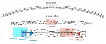
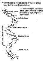
- the lathe carriage moves only horizontally, parallel to the radius of the disc defining the variable pitch of the spiral (imaginary axis of the real groove)
- the cantilevered cutting tool, attracted by the coils at 45 according to the electromagnetic signal, moves on an (imaginary) sphere by engraving the lacquer with a sinusoidal groove both in height and in width (stereo)
To do this, the cutting tool rotates with respect to its pivot by significant angles. This determines that the axis of the real groove diverges somehow, moment by moment, from the axis of the imaginary spiral.
To ensure that the stylus tip of our cartridge is aligned with the signal groove at the same angles as the cutting tool, it is necessary that, moment by moment:
- the head shell is aligned with the imaginary spiral in the same position as the lathe carriage head. A very difficult condition to achieve for both P TA and L TA and PL TA, due to the problems we all know even too well
- the cantilever has the same length as that of the cutting tool, in order to achieve the same inclinations, thus aligned with the center of groove (unfortunately there seems to be no established standards)
Of course, in order to replicate the movements of the cutting tool, in addition to the physical imperfections of the engraving, remains the fact that we have a passive movement vs an active one.
That such contraption could work is really a fascinating mechanical voodoo. Happy centenary Mr Blumlein, you were really a genius
carlo
hope the sketch could be clearer than my words- it's clearly exaggerated to evidence the geometric problems- practically, quote Doug, no possible issues, our problem is to get the headshell where it must. and the cantilever not bent.
Attachments
Last edited:
Stereo Lab has a video
Stereo Lab vinyl disc distortion cancellation - YouTube
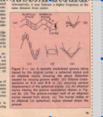
explaining the various distortion mechanisms inherent in stereo LP replay. Lateral tracking error distortion is discussed early and the video spends most of the time explaining the pinch effect and vertical tracing distortion which are stylus profile dependent. Their software claims to undo the effect of all three distortions and they appear to have a genuine software based solution which incidentally, is of no interest to me. However they do have a considerable track record of investigating the replay distortions and their explanation of pinch effect is contradictory to some of the recent comments. In particular the cutting stylus does not appear to change its alignment dependent on the modulation as suggested in the posts above. Indeed, if it did swing in response to the modulation, the pitch effect would not exist. Given that they are promoting an advanced solution resulting from many years of development and they work closely with cutting lathes and have intimate knowledge of the technology, I am inclined to question some of the reasoning and conclusions above. I am no expert, just seeking a better understanding.
Stereo Lab vinyl disc distortion cancellation - YouTube
explaining the various distortion mechanisms inherent in stereo LP replay. Lateral tracking error distortion is discussed early and the video spends most of the time explaining the pinch effect and vertical tracing distortion which are stylus profile dependent. Their software claims to undo the effect of all three distortions and they appear to have a genuine software based solution which incidentally, is of no interest to me. However they do have a considerable track record of investigating the replay distortions and their explanation of pinch effect is contradictory to some of the recent comments. In particular the cutting stylus does not appear to change its alignment dependent on the modulation as suggested in the posts above. Indeed, if it did swing in response to the modulation, the pitch effect would not exist. Given that they are promoting an advanced solution resulting from many years of development and they work closely with cutting lathes and have intimate knowledge of the technology, I am inclined to question some of the reasoning and conclusions above. I am no expert, just seeking a better understanding.
Last edited:
Stereo Lab has a video
Stereo Lab vinyl disc distortion cancellation - YouTube
Indeed, if it did swing in response to the modulation, the pitch effect would not exist.
Not true. Although the chisel swings the pinch effect exists.
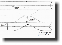
I calculated the wavelength of a sinusoidal signal on the disc (sure it has been done many times before):
frequency = 20 kHz
rotational speed: 33 1/3 1/min = 100/180 1/s
inner groove diameter: 120 mm
inner groove length: 380 mm
stylus path in 1 s : 380 x 100/180 mm = 210 mm
one period of 20 kHz signal : 0.01 mm = 10 μm
Compare it with the contact area dimensions of various styli e.g on the Soundsmith page:
Elliptical vs Conical Styli- Vinyl Engine
Bear in mind that that the typical signal level at high frequencies is low, in order to prevent inner groove distortion. At medium and lower frequencies the phase distortion (L-R phase difference due to groove modulation and "moving" contact points of a conical stylus) is much lower, because of the longer wavelength.
On reflection, I now agree. The pinch effect is solely due to the mismatch between the profiles of the cutter stylus and the cartridge stylus.Not true. Although the chisel swings the pinch effect exists.
I do think that the conversation is getting away from the issue of pivoting tonearm tangential alignment. I have been guilty of this too. This thread was more about matching the alignment of the cutter head IMO. I consider Straight Trackers definition to be a clear and achievable goal.
What you are describing there is tracing distortion not the rather separate issues with tracking.
There is a whole pile of fascinating stuff on predistorting to correct for this error on playback in the AES Disk cutting anthology, volume II as I recall.
The implementations back then (IIRC Columbia had one as did Decca) were not popular, mainly because the implementation of a variable delay line was not easy back then, but also because you inherently have to make assumptions about the playback stylus geometry.
BTW: You really, really don't want the playback stylus to look anything like the cutting one, it would absolutely shred the groove wall.
The Cantilever in a feedback cutting head is typically a few cm long! The requirements of a cutter are NOT the same as the needs of replay, and the geometry is (and must be) different.
Bear in mind that that the typical signal level at high frequencies is low, in order to prevent inner groove distortion. At medium and lower frequencies the phase distortion (L-R phase difference due to groove modulation and "moving" contact points of a conical stylus) is much lower, because of the longer wavelength.
The maximum level you can cut at high frequency is required to be severely limited by several factors.
There is an absolute limit on the radial velocity of the cutting stylus due to the back angle on the cutter and the need to not destroy the groove wall you have just cut.
Typically the cutter has a 45 degree rear profile on each side, so you are inherently limited by the need to keep the radial velocity at all times below the tangential velocity.
It is actually slightly worse then this because of the cutting angle you ned to limit to a slightly lower value in practise.
Since the output of the IRIAA circuit is velocity, and the IRIAA is rising at 6dB/octave up where it matters, this corresponds to a limit on maximum level that falls at 6dB/octave from about 2kHz.
Then you have the limit imposed by the osculating circle of the playback stylus, not everyone is running line contact, so you have to cut assuming playback on some skeevy Crossley with a ceramic pickup..... This imposes a -6dB/octave velocity limit from somewhere up about 5 - 8kHz or so depending on how conservative you are feeling, translating to pre IRIAA that is a -12dB/octave limit line.
Finally, acceleration is proportional to velocity and frequency, current is proportional to acceleration, and heat in the cutter head drive coils goes as current squared!
Even respecting the limits due to the geometry, lathe operators get real twitchy about cutting stuff that has significant high frequency content, because a burned cutter head is an expensive repair, some heads even run in a helium atmosphere to improve the cooling.
I don't think they get twitchy, they just preprocess the master file to knock down the level so it stays within the cutter limits - I can't imagine there isn't software specifically addressing this and other disc-mastering issues. I doubt its an issue other than for 12" 45rpm singles anyway (I've seen groove spacings of 1mm on those!)
The trick in a decent set of lathe electronics is that the power amplifier runs a few hundred mV of DC offset at the output which allows an impedance bridge to measure the drive coil resistance and hence winding temperature.
Typically the circuit trips the amp output relay open at 200 degrees c.
It USUALLY saves the head, but trashes the cut.
There is a frequency selective de-esser in the chain as well, typically before the IRIAA and feedback compensation boards.
You get earache about wanting it to be louder, but for Vinyl, louder mostly comes from mixing to the formats many, many limitations rather then anything the mastering or cutting engineer can do after the fact.
Yea software exists, but annoyingly enough of the market for disks insists on AAA that you cannot always deploy the generally very good DSP processing for marketing reasons...
Hope the 1mm pitch is an exaggeration, maximum modulation is about 100um, and even a stupidly deep cut is only going to add another 50um for the width of the groove itself.
I am guessing dance music of some form?
Ralf,
I didn't read your first post carefully enough and missed your point about terminology. I agree with you that a bit more descriptive precision would be helpful. I like Trenton's suggestion, but think we're too many years into this to make the switch.
Carlo,
Thanks for the sketch. It presents my conclusions very clearly. Up until Ralf posted his question, I never gave much thought to the uM scale behavior of either the cutter or the stylus and their relative alignments to the groove. Maybe too much thought. My wife said "you've always been a bit of a nut about this stuff, but never like this."
dmills,
Thanks for your contributions. I understand more now that cutting head geometry is different from play back geometry, but would you comment on posts #44 and # 45, please? Are they even close? Centimeters-long cantilevers? I can't imagine how that would work. RE "cutting for a skeevy Crossly:" Does that mean a decent conical might ride that groove fairly decently?
I've attached a couple of the ubiquitous illustrations of cutting heads and stylus types in grooves. I'm beginning to question their usefulness.
Attachments
Last edited:
Obsessing over the geometric differences between the cutting stylus and the cartridge profiles in a random groove, is a distraction. There are far too many unknowns. Which cutting stylus and cartridge profile? Which groove modulation? Which cutting engineer?
Allowing the replay cartridge cantilever to sit tangentially to a locked circular groove at any radius should be the first order of business as Straight Tracker suggested in another thread. Even with this clear and simple aim, there will be impediments like imperfect stylus and/or cantilever alignment. This can occur with brand new premium cartridges and can also creep in over time with use. Then there are the LP imperfections.
The discussion over tonearm geometry in relation to cutting stylus geometry and cantilevers is analogous to designing a car steering by considering the following of random curves and humps without first getting it to steer in a straight line on a flat surface.
Hope the sketch could be clearer than my words- it's clearly exaggerated to evidence the geometric problems- practically, quote Doug, no possible issues,. # 45
My sketch could maybe mislead someone, sorry: my aim was to examine the thing just from a geometric point of view by highlighting that, even if it's commonly said that the cutting tool acts in parallel, this is not geometrically true since it is mounted on a cantilever rotating on a pivot.
This was shown altering completely the proportions: doing in real ones the cutting head (too big), or the groove (too small) could not be seen together on the same sketch.
In practice, as Doug previously noted, the cantilever length/sinusoid amplitude ratio - mm vs micron 1000:1 - is such as to make the problem irrelevant for sound reproduction.
But not for theoretical assessments.
carlo
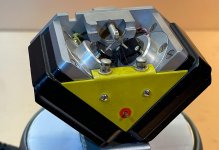
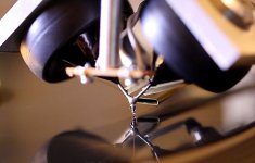
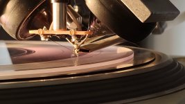
Hi guys. Look at the pictures. There is no pivoting cantilever in the cutting heads  . Many more pics of the Neumann SX-68 NEUMANN SX 68 stereo CutterHead for Vinyl Cutting NEUMANN VMS Lathe | eBay
. Many more pics of the Neumann SX-68 NEUMANN SX 68 stereo CutterHead for Vinyl Cutting NEUMANN VMS Lathe | eBayAttachments
dagfinn said:There is no pivoting cantilever in the cutting heads
Hi dagfinn,
If you look very carefully at your first picture, you will see a massive half cylindrical metal block towards the rear of the cutter head. At the front of that block, you will see a "C" shaped half cylindrical clamp. Sandwiched between those two components, there is a spring-steel flexure that is connected to what looks like a cantilever. There also is an elastomer connected to the cantilever right behind the point where the flexure is connected. This is not visible but I think the rear of the elastomer has a metal stud bonded to it which is held in place by the plainly visible set screw. So I think the cantilever "pivots" if you can call it that.
Sincerely,
Ralf
- Home
- Source & Line
- Analogue Source
- Thoughts on "tracking tangentially to the groove"