Hello,
As a learning project to push myself into starting to design my own stuff rather I have been trying to come up with (yet another) phono stage.
I wanted something with a balanced input b/c I think the superior CMMR is worth it in my particular case. I do have quite a bit of EMI where I'm listening to records. So my design goals:
- Optimized for MM. (For MC carts, a head-amp can be added later)
- Balanced input to cancel out CM interference
- Keep capacitors out of the signal path as much as possible
- passive RIAA
- Optional sub-sonic/rumble HPF
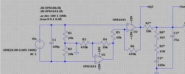
So using what I've learned so far about op-amps and looking at what many others did, I've put something tohether in LTSpice.
I'm using an offset compensation through another op-amp in order to get rid of the DC offset introduced in the initial two stages.
The rumble filter is a 3rd order S-K Q=.707 filter with a 20Hz cutoff. The idea is to have switch that selects the output jacks to either connect to U3 directly (out1) or to alternatively to the HPF output (out2)
Resistors in the RIAA filter should be .1% types and the caps there should be 3% types.
I think I'm pretty ignorant about all the things I don't know yet, so if someone can spare a few minutes to look at this thing and can share some feedback on what to do differently that would be awesome...
Some points I'm wondering about in particular:
- Better choices for op-amps?
- Is it worth considering a discrete approach for the first stage instead of op-amp
- is a a good idea to place the HPF as the last piece of the chain? Would there be anything advantegeous about putting it between the RIAA and the second gain stage?
- is the offset compensation a worthwhile approach or should a DC blocking cap in the output be considered. It might just be a matter of taste, but I'd love to read opinions on this...
- Is there a better way to wire up the input to have best flexibility with balanced and single-ended sources? Also modifications to the input loading resistance and capacitance (R1/R2, C1) are interesting to me. How can that be put into practice? Some RCA jacks in parallel where one could fit caps and resistors seems to be one way to go about that but the fact that the resistive load is split across R1/R2 makes this more complicated. Is there a way to have a single load resistor and still have a balanced input?
Here's the schematic and a bode plot w/ and w/o HPF

Cheers,
Lars
As a learning project to push myself into starting to design my own stuff rather I have been trying to come up with (yet another) phono stage.
I wanted something with a balanced input b/c I think the superior CMMR is worth it in my particular case. I do have quite a bit of EMI where I'm listening to records. So my design goals:
- Optimized for MM. (For MC carts, a head-amp can be added later)
- Balanced input to cancel out CM interference
- Keep capacitors out of the signal path as much as possible
- passive RIAA
- Optional sub-sonic/rumble HPF
So using what I've learned so far about op-amps and looking at what many others did, I've put something tohether in LTSpice.
I'm using an offset compensation through another op-amp in order to get rid of the DC offset introduced in the initial two stages.
The rumble filter is a 3rd order S-K Q=.707 filter with a 20Hz cutoff. The idea is to have switch that selects the output jacks to either connect to U3 directly (out1) or to alternatively to the HPF output (out2)
Resistors in the RIAA filter should be .1% types and the caps there should be 3% types.
I think I'm pretty ignorant about all the things I don't know yet, so if someone can spare a few minutes to look at this thing and can share some feedback on what to do differently that would be awesome...
Some points I'm wondering about in particular:
- Better choices for op-amps?
- Is it worth considering a discrete approach for the first stage instead of op-amp
- is a a good idea to place the HPF as the last piece of the chain? Would there be anything advantegeous about putting it between the RIAA and the second gain stage?
- is the offset compensation a worthwhile approach or should a DC blocking cap in the output be considered. It might just be a matter of taste, but I'd love to read opinions on this...
- Is there a better way to wire up the input to have best flexibility with balanced and single-ended sources? Also modifications to the input loading resistance and capacitance (R1/R2, C1) are interesting to me. How can that be put into practice? Some RCA jacks in parallel where one could fit caps and resistors seems to be one way to go about that but the fact that the resistive load is split across R1/R2 makes this more complicated. Is there a way to have a single load resistor and still have a balanced input?
Here's the schematic and a bode plot w/ and w/o HPF
Cheers,
Lars
Opamps and passive RIAA equalization not optimal due to the likelihood of over-loading at the high frequency end of the audio band. You can tame this by lowering the values of R1/R2 to take into consideration the inductance of the cartridge. This puts the 75uS compensation before the first stage of amplification.
Bob Cordell demonstrated in his "VinylTrak" phono preamp in Linear Audio Volume 5.
Of course, the values of the rest of the compensation network change.
Bob Cordell demonstrated in his "VinylTrak" phono preamp in Linear Audio Volume 5.
Of course, the values of the rest of the compensation network change.
The 10k values of R4 and R5 are high and contribute a lot of noise, about 18nV/√Hz according to my calcs. That's much more noise than the OPA1641 devices you've selected.Here's the schematic
perhaps R4=R5= 470 ohms and R3=R6= 22k would be better, reducing the Johnson noise contribution to 3.9nV/√Hz.
The 10k values of R4 and R5 are high and contribute a lot of noise, about 18nV/√Hz according to my calcs. That's much more noise than the OPA1641 devices you've selected.
perhaps R4=R5= 470 ohms and R3=R6= 22k would be better, reducing the Johnson noise contribution to 3.9nV/√Hz.
This is very useful advice. Much appreciated, Mark!
LTSpice noise sim with original 10k/470k

and with 470R/22k as suggested...

Last edited:
Opamps and passive RIAA equalization not optimal due to the likelihood of over-loading at the high frequency end of the audio band. You can tame this by lowering the values of R1/R2 to take into consideration the inductance of the cartridge. This puts the 75uS compensation before the first stage of amplification.
Bob Cordell demonstrated in his "VinylTrak" phono preamp in Linear Audio Volume 5.
Of course, the values of the rest of the compensation network change.
Putting that pole into the input/loading makes it dependent on the exact cartridge model, doesn’t it?. I like to switch around cartridges so that’s not very practical.
Can you talk a bit more to what sort of overloading is potentially happening with opamps and passive RIAA? I don’t really know what I’m doing so this is one more thing I have no clue about. Hopefully I can learn…
Can you talk a bit more to what sort of overloading is potentially happening with opamps and passive RIAA? I don’t really know what I’m doing so this is one more thing I have no clue about. Hopefully I can learn…
It's been discussed on DIYAUDIO and elsewhere -- while there isn't a lot of audio information above 10kHz, the recording physics/mechanics dictate that the output at 20kHz will be 10x the output at 1kHz.
The surface noise, clicks and pops, can overwhelm the first gain stage, causing it to distort.
Search the web for articles on "phono stage headroom"
If you change R7 (in your diagram), you can use 3x 1% polypropylene caps for the RIAA equalisation;...Resistors in the RIAA filter should be .1% types and the caps there should be 3% types.
KAB RIAA Computer
100nF 1% Polypro... (I've yet to find 200nF 1% Polypro...s)
68nF 1% Polypro...
https://www.diyaudio.com/forums/attachment.php?attachmentid=1000878&stc=1&d=1638051465
R3=470k!

I'm guessing, but I'm reasonably sure that a standard 'instrumentation amplifier' front end with lower value resistors (as already suggested) would be quieter... And better balanced!
See this.
Good Luck!
Attachments
If you change R7 (in your diagram), you can use 3x 1% polypropylene caps for the RIAA equalisation;
KAB RIAA Computer
100nF 1% Polypro... (I've yet to find 200nF 1% Polypro...s)
68nF 1% Polypro...
https://www.diyaudio.com/forums/att...-mm-phono-pre-balanced-input-almost_inamp-jpg
R3=470k!
I'm guessing, but I'm reasonably sure that a standard 'instrumentation amplifier' front end with lower value resistors (as already suggested) would be quieter... And better balanced!
See this.
Good Luck!
Yes thanks for pointing that out. Both about the 1% Caps and the FrontEnd. The 470k was something I re-used from an example not thinking about the noise it would cause. That can clearly be reduced as mentioned above. However, using a monolithic in-Amp like INA163 is probably even better.
I also think that I have been convinved that the advantages of a passive RIAA are much more mythical then they are real and I think I will redraw this thing with active RIAA
Cheers!
I've tried to read up on a few things and tweaked my approach a bit.
For the front-end I'm now using a monolithic in-amp INA163 instead of building a 2- or 3-op-amp instrument amplifier built up from individual op-amps.
I've played with various approaches on the RIAA EQ and I've settled on a variant of the Baxendall Active/Passive. I'v put the 2122 Hz Pole in front of the active part to allow for more OLM on the higher frequencies. Assuming 12V max output and 5 mV nominal output cartridge there should be roughly 27.7 dB headroom. The in-amp gain could be raised a bit more if needed. I don't see a lot of advantage in putting in additional gain stage after the RIAA.
RIAA conformance is within +/-0.015 dB.
The 3rd order S-K filter with a 20 Hz Cutoff would be swicthable. I would also plan for an additional switch that parallels equal size resistors with R/R/R10 which would raise the cutoff freq to 40 Hz which is useful for some older classical recordings that suffer from some severe low-frequency rumble that isn't effectively addressed by the 20Hz filter.
I've experimented a bit with using a servo hooked up to the INA136 ref pin to cancel out DC offset. In the end, I think it's not worth it. It boils down to some sort of low-pass filter that is giving negative feedback to the in-amp via the ref pin. I don't think that's any worse then just putting a good cap for DC blocking into the output.

Any thoughts/feedback/suggestions would be much appreciated...
Cheers!
Lars
For the front-end I'm now using a monolithic in-amp INA163 instead of building a 2- or 3-op-amp instrument amplifier built up from individual op-amps.
I've played with various approaches on the RIAA EQ and I've settled on a variant of the Baxendall Active/Passive. I'v put the 2122 Hz Pole in front of the active part to allow for more OLM on the higher frequencies. Assuming 12V max output and 5 mV nominal output cartridge there should be roughly 27.7 dB headroom. The in-amp gain could be raised a bit more if needed. I don't see a lot of advantage in putting in additional gain stage after the RIAA.
RIAA conformance is within +/-0.015 dB.
The 3rd order S-K filter with a 20 Hz Cutoff would be swicthable. I would also plan for an additional switch that parallels equal size resistors with R/R/R10 which would raise the cutoff freq to 40 Hz which is useful for some older classical recordings that suffer from some severe low-frequency rumble that isn't effectively addressed by the 20Hz filter.
I've experimented a bit with using a servo hooked up to the INA136 ref pin to cancel out DC offset. In the end, I think it's not worth it. It boils down to some sort of low-pass filter that is giving negative feedback to the in-amp via the ref pin. I don't think that's any worse then just putting a good cap for DC blocking into the output.
Any thoughts/feedback/suggestions would be much appreciated...
Cheers!
Lars
Last edited:
...monolithic in-amp INA163...
https://www.ti.com/lit/ds/symlink/ina163.pdf said:NOISE PERFORMANCE
The INA163 provides very low-noise with low-source impedance. Its 1nV/√Hz voltage noise delivers near theoretical noise performance with a source impedance of 200Ω. The input stage design used to achieve this low noise, results in relatively high input bias current and input bias current noise. As a result, the INA163 may not provide the best noise performance with a source impedance greater than 10kΩ. For source impedance greater than 10kΩ, other instrumentation amplifiers may provide improved noise performance.
The effective impedance of a phono cart is unclear, obviously varies, and is open to debate (I hear the flames coming). IMHO you are on the edge of where thermal hiss may wipe-out much of the intended benefit from balanced operation. Note that most of the benefit of balance can be had by careful site selection (not near the electric train tracks) and meticulous shielding. Yes, sometimes we must take the site as-is, and sometimes too much shielding is not enough. An interesting experiment.
Hi,
yes, the INAs are optimized for lower impedance values than the typical MM cartidge offers, but with still low enough current noise figures such that noise remains inaudible in praxis.
Balanced inputs with MM cartridges may be debatable anyway as MM generators wouldn´t be truely balanced and many are additionally artifically unbalanced by the manufacturer.
The nice thing about he INAs is that You can easily make the input switchable between blanced and unbalanced.
I´d still opt for the dc-servo to the INAs Ref-input.
It keeps the commonmode voltage on the internal ´third OPA´ low and guarantees for lowest dc-offset at the INAs output ... thereby preserving the highest overload margin to the second stage and forming a first subsonic filter at the same.
jauu
Calvin
I think I'm a bit out of my depth getting the servo setup quite right.
When I get it to servo out enough of the offset, it is too heavily interacting with the RIAA curve by attenuating low frequencies and if I make the timeconstant such that it doesn't mess with the curve too much, it does not seem to counteract the offset quite enough.
Then I am not really sure about the fundations from which to approach this.
I think it needs to look somewhat like this...

I think in general we're supposed to be integrating (inverse) the output of the second stage and have a resistor (R14) accross C7 so that we don't run against the rail. So it essentially becomes an inverting high-pass.
Obviously, my knowledge gets fuzzy here. Maybe you have some pointers for me...
Cheers!
Lars
When I get it to servo out enough of the offset, it is too heavily interacting with the RIAA curve by attenuating low frequencies and if I make the timeconstant such that it doesn't mess with the curve too much, it does not seem to counteract the offset quite enough.
Then I am not really sure about the fundations from which to approach this.
I think it needs to look somewhat like this...
I think in general we're supposed to be integrating (inverse) the output of the second stage and have a resistor (R14) accross C7 so that we don't run against the rail. So it essentially becomes an inverting high-pass.
Obviously, my knowledge gets fuzzy here. Maybe you have some pointers for me...
Cheers!
Lars
Your servo is alow pass with a gain of 1/10th and a corner frequency of 159 Hz.
So your feedback loop eliminates all frequencies below 159 Hz and due to the low gain does not really cancel the DC offset
Leave out the ressitor across the cap and increase the 10 k resistor to 100 k. This will form a fedback loop with a 1.59 Hz corner frequency.
So your feedback loop eliminates all frequencies below 159 Hz and due to the low gain does not really cancel the DC offset
Leave out the ressitor across the cap and increase the 10 k resistor to 100 k. This will form a fedback loop with a 1.59 Hz corner frequency.
Thanks! Thats the topology I tried originally but that was interacting with the RIAA in a way that didn't seem quite right.
With 100k it gives quite a bit of a like a resonance bump at about 100Hz

If I use 5Meg (fc=0,03 Hz I think), it flattens that out much better but I'm not quite sure if that is where we want to land...

With 100k it gives quite a bit of a like a resonance bump at about 100Hz
If I use 5Meg (fc=0,03 Hz I think), it flattens that out much better but I'm not quite sure if that is where we want to land...
The effective impedance of a phono cart is unclear, obviously varies, and is open to debate (I hear the flames coming).
See the attachment - no flames, just integrals, square roots and numbers.
Attachments
Regarding the DC feedback, there is an amplifier with a gain of 102.372549 up to approximately 50 Hz in the forward path of the DC feedback loop, so to get a corner frequency of for example 5 Hz, you need an integrator with an RC product of 102.372549/(2 pi 5 Hz). When C = 1 uF, that boils down to R = 3 258 619.443 ohm. So that 5 Mohm is in the right ballpark, it should give you a -3.01 dB point of roughly 3.26 Hz. (The corner frequency occurs where the DC feedback loop runs out of loop gain, so the more gain there is elsewhere in the loop, the slower the integrator needs to be.)
Another issue is that the poles of the correction stage will be shifted by the DC feedback loop. If you want to get it really accurate, you have to treat the combination of the RIAA correction stage and the DC feedback loop as a third-order filter, calculate its characteristic polynomial (denominator of its transfer function) and equate the coefficients to the values that you want to have. Either that or just tweak the RIAA correction values a bit until you are close enough.
Another issue is that the poles of the correction stage will be shifted by the DC feedback loop. If you want to get it really accurate, you have to treat the combination of the RIAA correction stage and the DC feedback loop as a third-order filter, calculate its characteristic polynomial (denominator of its transfer function) and equate the coefficients to the values that you want to have. Either that or just tweak the RIAA correction values a bit until you are close enough.
Last edited:
Regarding the DC feedback, there is an amplifier with a gain of 102.372549 up to approximately 50 Hz in the forward path of the DC feedback loop, so to get a corner frequency of for example 5 Hz, you need an integrator with an RC product of 102.372549/(2 pi 5 Hz). When C = 1 uF, that boils down to R = 3 258 619.443 ohm. So that 5 Mohm is in the right ballpark, it should give you a -3.01 dB point of roughly 3.26 Hz. (The corner frequency occurs where the DC feedback loop runs out of loop gain, so the more gain there is elsewhere in the loop, the slower the integrator needs to be.)
Another issue is that the poles of the correction stage will be shifted by the DC feedback loop. If you want to get it really accurate, you have to treat the combination of the RIAA correction stage and the DC feedback loop as a third-order filter, calculate its characteristic polynomial (denominator of its transfer function) and equate the coefficients to the values that you want to have. Either that or just tweak the RIAA correction values a bit until you are close enough.
Thanks, I'm sort of leaning more and more to just sticking with a good cap in the output rather than dealing with the servo...
What I found is that if I apply the DC feedback at the second stage, at least in the simulation I'm not getting that interaction between those filters and the RIAA conformance stays where it was when I ran without the servo...
View attachment 1002158
It still seems to work well for canceling the DC offset after the 2nd stage.
View attachment 1002157
Here it is without the servo wihe the DC offset over the two stages compunding to 200 mV due to the high (60 dB) gain at low-frequencies/DC.
View attachment 1002159
Why isn't the servo interacting with the RIAA EQ in the same manner as before in this topology. Is this simply because we don't apply the 1st stage gain to the inegrators output?
For some reason your attachments don't work, I only get a message that I should contact a system administrator and when I do, I get an error message.
The shifting of the poles of the RIAA correction stage that I wrote about, only happens when you put the feedback loop around the RIAA correction stage. It is related to the correction stage being put in a loop of which the loop gain isn't exactly zero yet at the corner frequencies of the RIAA network, particularly the first corner.
I can write a more extensive explanation with lots of polynomials if that helps. Not now, though, I'm going to sleep.
I wonder what happened to those attachments...
What I tried was making the DC-correction through negative feedback into the 2nd (riaa) stage. (inverse) inegrating over the riaa would yield a value proportional to the DC component. We sum 1% of that at the input to the riaa stage's op-amp and it would counteract the DC component at that output. When the DC component goes down, the result of the integration becomes smaller in magnitude and so it balances...
This way, it does seem to not mess with the RIAA EQ and it stays within the original 0.05 dB conformance margin that I had before:

Even with a hefty 10mV DC offset added to the input, it balances that out. At least in simulation. That 10mV becomes 10V after the combined 60dB DC gain of the two stages. So the servo goes to -10V b/c 1% of that -1V is added to the riaa stage's (U3) input which counteracts the +1V that the in-amp outputs due to it's DC gain of 20 dB

I was expecting that I was oversimpifying things (once more) and that there would still be complex interaction with the RIAA filter but it simulation it looks pretty straight forward. Can I expect this to work in practice?
By adjusting R14 the ratio (R2:R14) with which the servo's correction signal gets summed into the RIAA stage can be adjusted. The higher the ratio, the less output the servo needs to provide to counteract the offset. On the other hand, since it's also high-pass filter (fc=1/(2*pi*C7*R13)) it will also attenuate low frequencies. With the chosen RC the transferfunction at 20 Hz (7950µs) is 0.00013 V/V we take 1% of that which is 0,0000013 or -0.0000113 dB of attenuation at 20 Hz. If that thinking is correct, that should be all good.
What I tried was making the DC-correction through negative feedback into the 2nd (riaa) stage. (inverse) inegrating over the riaa would yield a value proportional to the DC component. We sum 1% of that at the input to the riaa stage's op-amp and it would counteract the DC component at that output. When the DC component goes down, the result of the integration becomes smaller in magnitude and so it balances...
This way, it does seem to not mess with the RIAA EQ and it stays within the original 0.05 dB conformance margin that I had before:
Even with a hefty 10mV DC offset added to the input, it balances that out. At least in simulation. That 10mV becomes 10V after the combined 60dB DC gain of the two stages. So the servo goes to -10V b/c 1% of that -1V is added to the riaa stage's (U3) input which counteracts the +1V that the in-amp outputs due to it's DC gain of 20 dB
I was expecting that I was oversimpifying things (once more) and that there would still be complex interaction with the RIAA filter but it simulation it looks pretty straight forward. Can I expect this to work in practice?
By adjusting R14 the ratio (R2:R14) with which the servo's correction signal gets summed into the RIAA stage can be adjusted. The higher the ratio, the less output the servo needs to provide to counteract the offset. On the other hand, since it's also high-pass filter (fc=1/(2*pi*C7*R13)) it will also attenuate low frequencies. With the chosen RC the transferfunction at 20 Hz (7950µs) is 0.00013 V/V we take 1% of that which is 0,0000013 or -0.0000113 dB of attenuation at 20 Hz. If that thinking is correct, that should be all good.
- Home
- Source & Line
- Analogue Source
- MM Phono Pre with balanced input