Hi Bonsai,
Nice design for a transimpedance amp without feedback, but a few comments:
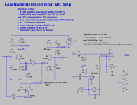
With 100R collector resistors and 1.8V on them, Ic=18mA.
Total input resistance is 2*Rbb +2*(1/2Gm) = 2*1.5 + 2*(1/1.44) = 4.4R
This 4.4R will produce 0.27nV/rtHz, very close to what you specified.
With a 1R Cart, gain is indeed 100/1 = 100.
But taking a 10R Cart, gain is not 100/10=10 but 30.
Hans
Thanks Hans.
I haven’t done all the gain calcs etc as you have done, so thanks for doing this. Indeed, you have to take the input resistance into the gain equation (see for example the X-Altra MC/MM preamp where this is also discussed). The figures I quoted above are just first cut numbers in an idealized situation. There’s probably some more work from my side for noise optimization, but see my comments on the next post
Last edited:
Most balanced input preamplifier specify a high input resistance wrt to the assumed source and cabling resistance. This is because any input impedance load imbalance can cause the resultant imbalance fraction of the common mode signal to appear as a differential signal ie unwanted noise.
The problem with this preamp that needs to be checked further is that the input impedance is very low and related to re’ which is about 1.4 ohms per transistor, total 2.8 ohms - these figures dependent upon the collector current as discussed above by Hans.
This is exactly the opposite of what you want in a balanced input amp. However, the source resistance is low, and any capacitive common mode coupling only a few pF so the generated noise is low. Magnetic coupling will be more difficult to deal with.
As I noted in the first post, more work is needed and the acid test is what happens if connect a cable to the input and then hold the bare wires on the other end. On an unbalanced input phono amp, you will get severe hum, on a balanced input you should get very little or none.
")
The problem with this preamp that needs to be checked further is that the input impedance is very low and related to re’ which is about 1.4 ohms per transistor, total 2.8 ohms - these figures dependent upon the collector current as discussed above by Hans.
This is exactly the opposite of what you want in a balanced input amp. However, the source resistance is low, and any capacitive common mode coupling only a few pF so the generated noise is low. Magnetic coupling will be more difficult to deal with.
As I noted in the first post, more work is needed and the acid test is what happens if connect a cable to the input and then hold the bare wires on the other end. On an unbalanced input phono amp, you will get severe hum, on a balanced input you should get very little or none.
Your point is valid, and I would need to look into this. I’ve seen some of the more experienced guys here talk about a few hundred uA at start up not being a problem. Under normal circumstances there is only a few uV max across the coil and related to the servo amp offset - the OPA2188/9 are superb in this regard.
However, any phone stage that servos the input will have this issue, as will those that use input caps that have to charge up.
However, any phone stage that servos the input will have this issue, as will those that use input caps that have to charge up.
Last edited:
I like the look of this. So gain is R3/Rcart, so 10x for a 10 Ohm cartridge, less for a cart with higher resistance. You mention different idle currents, how do you adjust that? Do you need to change all of R1-R4 to adjust the idle current or the gain? Does PS voltage matter gain and idle current? How much current can you push through those Zetex semis without heat sinks, and will sinks allow one to use higher current?
Sorry for the silly questions but this is an unusual (to me) circuit and I do not understand it.
For the gain adjustment you would place a resistor string in each collector of total say 500 Ohms per side with 4 or 5 tap off points and simply select the tap you needed for the required gain.
The gain is related to the cartridge resitance and the collector load - you do need to include the emitter resistance in the gain calc because it is significant and especially so with low R carts.
I will do some more work on this and flesh it out over the next few weeks.
Since you are connecting the emitters to the Cart, there is an undefined situation at start up and shut off where any current could flow through the Cart, indeed a serious problem.Most balanced input preamplifier specify a high input resistance wrt to the assumed source and cabling resistance. This is because any input impedance load imbalance can cause the resultant imbalance fraction of the common mode signal to appear as a differential signal ie unwanted noise.
The problem with this preamp that needs to be checked further is that the input impedance is very low and related to re’ which is about 1.4 ohms per transistor, total 2.8 ohms - these figures dependent upon the collector current as discussed above by Hans.
This is exactly the opposite of what you want in a balanced input amp. However, the source resistance is low, and any capacitive common mode coupling only a few pF so the generated noise is low. Magnetic coupling will be more difficult to deal with.
As I noted in the first post, more work is needed and the acid test is what happens if connect a cable to the input and then hold the bare wires on the other end. On an unbalanced input phono amp, you will get severe hum, on a balanced input you should get very little or none.
But for every problem there is a solution.
To start with, the base voltage of Q2 should be firmly defined, since it's now dependent on the Hfe of Q2.
When connecting the bases of Q1 and Q2 with a 33R resistor, emitters will come up and go down in a much better defined way and the servo, remaining as is, will alter the base voltage of Q1 in the mV range only, enough to compensate for transistor differences.
But even then, at start up a few mV can exist between emitters, leading to several mA for a low Rs Cart.
Now not connecting the 100R emitter resistors to gnd but placing a mosfet//10K in between, an RC network between gnd and V+ (their midpoint connected to the gate) could make the mosfet//10K gradually go from 10K into mOhm, thereby seemingly disappearing.
At shut off a diode can immediately discharge the RC network and the transistors are conducting together at 180uA instead of 18mA each.
This should prevent any mishap.
Just a few ideas.
Hans
Last edited:
Sorry I mixed up my re’ and rb’ earlier. Rb’ is the noise contributor, not re’
Yes Re is also contributing to the noise as 1/2Gm where Re is the inverse of Gm.
Noise in total is produced by (Rb + 1/2Gm) or (Rb + Re/2)
Hans
I like the look of this. So gain is R3/Rcart, so 10x for a 10 Ohm cartridge, less for a cart with higher resistance. You mention different idle currents, how do you adjust that? Do you need to change all of R1-R4 to adjust the idle current or the gain? Does PS voltage matter gain and idle current? How much current can you push through those Zetex semis without heat sinks, and will sinks allow one to use higher current?
Sorry for the silly questions but this is an unusual (to me) circuit and I do not understand it.
For the gain adjustment you would place a resistor string in each collector of total say 500 Ohms per side with 4 or 5 tap off points and simply select the tap you needed for the required gain.
The gain is related to the cartridge rests EC and the collector load - you do need to include the emitter resistance in the gain calc because it is significant and especially so with low R carts.
I will do some more work on this and flesh it out over the next few weeks.
I don't understand the balancing circuit U2/U3. U2 has a gain of 2 for the voltage on R9 (let's call its input U, output 2U). U3 just inverts this signal (output -2U) and adds the voltage on R11 (let's call it -U) with a gain of -1 (output U). The net output on U3 will be -2U+U= -U.
Why didn't you use a balancer like on a) or b) in this link?
Amplifiers with balanced Inputs or Outputs-TINA and TINACloud
Or just the second half of picture b) without the input buffers.
Hello,
The output from the MC front end is a balanced signal. The opamp stage is a standard balanced to unbalanced stage so it’s rejecting the common mode signal on the collectors and only pulling out the differential signal.
Since you are connecting the emitters to the Cart, there is an undefined situation at start up and shut off where any current could flow through the Cart, indeed a serious problem.
But for every problem there is a solution.
To start with, the base voltage of Q2 should be firmly defined, since it's now dependent on the Hfe of Q2.
When connecting the bases of Q1 and Q2 with a 33R resistor, emitters will come up and go down in a much better defined way and the servo, remaining as is, will alter the base voltage of Q1 in the mV range only, enough to compensate for transistor differences.
But even then, at start up a few mV can exist between emitters, leading to several mA for a low Rs Cart.
Now not connecting the 100R emitter resistors to gnd but placing a mosfet//10K in between, an RC network between gnd and V+ (their midpoint connected to the gate) could make the mosfet//10K gradually go from 10K into mOhm, thereby seemingly disappearing.
At shut off a diode can immediately discharge the RC network and the transistors are conducting together at 180uA instead of 18mA each.
This should prevent any mishap.
Just a few ideas.
Hans
Thanks - I’m thinking about some of these solutions. I have to keep it simple - as they say, ‘elegance is everything’
The amp consists of two stages - the input stage with discrete transistors and the opamp summing and output stage. If you have two stages in series, the overall noise basically is calculated as (input stage noise) + (output stage noise / gain of input stage). If the input stage has significant gain (which is the case in this amp), noise of the second stage does not contributes much to the overall noise !
Thnx. I am embarrassed b/c I know this... guess I had a brain-fart. I use the same opamps in a front end and from that had that opamp's input Vnoise(3.1nV)*gain stuck in my head.
Lol I thought the same... who draws signals going right to left..?Just rearranging so my head doesn't explode:
Hi,
did You check about the input offset OPAmp while powering up/down?
I'm always a bit weary about OPAs that require settling to an output voltage way off of 0V.
Whilst settling it could push some unwanted, possibly even destructive current through the source. I also had it -when the settling voltage had to be close to a supply line- that the servo eventually started up in the wrong direction, leading to a latch-up.
jauu
Calvin
- Home
- Source & Line
- Analogue Source
- Low noise Balanced MC Pre