Hello-
I have a NAD 712 that won't tune FM
AM is fine, but when switched to FM, although it runs up and down the frequencies as shown on the LCD, it's not actually tuning any stations - just white noise...THE CENTER Tune illuminates when a strong AM station is pulled in - center Tune never illuminates when manually tuning or scanning FM...
On closer inspection, there's a tuning control voltage which comes from pin 17 of the LM7000.
This is fine on AM (2.1V) , but as soon as FM is selected, this disappears to zero volts and I can't see why.
Any assistance is very appreciated!
Oh, I should mention I am a COMPLETE NOVICE....so please keep that in mind if you reply") also, I am armed only with a digital multimeter and a soldering iron, no scope....
also, I am armed only with a digital multimeter and a soldering iron, no scope....
I have a NAD 712 that won't tune FM
AM is fine, but when switched to FM, although it runs up and down the frequencies as shown on the LCD, it's not actually tuning any stations - just white noise...THE CENTER Tune illuminates when a strong AM station is pulled in - center Tune never illuminates when manually tuning or scanning FM...
On closer inspection, there's a tuning control voltage which comes from pin 17 of the LM7000.
This is fine on AM (2.1V) , but as soon as FM is selected, this disappears to zero volts and I can't see why.
Any assistance is very appreciated!
Oh, I should mention I am a COMPLETE NOVICE....so please keep that in mind if you reply
also, I am armed only with a digital multimeter and a soldering iron, no scope....
Last edited:
You need a tuner guy. You might manage to get lucky and fix the fault, but it will then need realignment. Youre not going to be able to sort this out yourself without RF gear.
+1 what he said.
Well you have identified the tuning voltage is wrong not changing. This could be that the LO in the tuner can IC702 is not working, it that is the case the hiss will be quieter than if its working. It may be no supply or there's a fault in the can. Its also possible the input filter is O/C too.
Check the 30V supply is present first, at R707 (or at C704) (page 17)
This is crucial for FM tuning.
31.9V at R707, is that OK?
Thanks everyone for your comments.
I found a Nad/tuner guy and he was very helpful but basically said it was not worth paying him to investigate/fix...that I should just buy a standalone tuner.
I probably will do that but I just wanted to poke around in case it was something obvious....
Has anybody worked on this (or a similar) Nad? I can’t even figure out how to get at the trace side...Taking bottom panel off still leaves tuner section inaccessible (as far as I can tell), maybe I better give up now
Voltage at R707 is 31.9. Is that OK?
Has anyone worked on this (or a similar) Nad? It’s got one big board with access thru bottom but after removing bottom panel, access to tuner section is limited. Is there a best way to further disassemble to gain access to trace side of tuner section?
Thanks to everyone for the replies. I did find a NAD/tuner guy and he was very helpful but said it was not worth it for me to pay him to investigate/repair. He recommended I just buy a used stand-alone tuner.
31.9V at R707, is that OK?
That's fine
Obviously confirm the other supplies are present +12 -12 +5 etc
Check the 12v specifically at R928, R933 to make sure this area of the tuning is getting supply etc
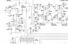
..next check for the variable tuning volt (in the range of that 30v rail i.e. a couple of volts at the bottom of the FM band and ~30V at the top) to the tuner can (Vc on the first pic attached)
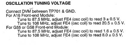
Also check/confirm the voltages are in the range (from bottom of the FM band to the top of the FM band) in the FM setup (shown in pic2 attached)
I agree just buy another tuner , FM aren't that dear secondhand
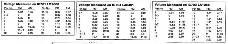
but if you really want to get to the bottom of it and repair then ^^There are also some useful pinouts of tuner IC's in the manual showing typical voltages around them - check those out to see what's not right and work back from there.
Attachments
Last edited:
Check also the voltages around IC702 (front end). VC you already established is zero which means that the local oscillator (LO) will be around 95 MHz. You should be able to pick this up by holding a portable next to the metal can. Also check V+. If you cannot receive any LO the front end is borked. Sometimes oscillators fail to start with VT at zero. If you do IC701 may be the culprit.
The reputation of NAD may be pants but this is still a nice tuner. That said, access to the copper side will prolly require complete disassembly. I've had many tuners needing that. But first check that LO.
Edit: Oh, it's a receiver...
The reputation of NAD may be pants but this is still a nice tuner. That said, access to the copper side will prolly require complete disassembly. I've had many tuners needing that. But first check that LO.
Edit: Oh, it's a receiver...
Last edited:
Obviously confirm the other supplies are present +12 -12 +5 etc
Check the 12v specifically at R928, R933 to make sure this area of the tuning is getting supply etc
R928 11.9
R933 11.9
Will try to check other supplies later today.
..next check for the variable tuning volt (in the range of that 30v rail i.e. a couple of volts at the bottom of the FM band and ~30V at the top) to the tuner can (Vc on the first pic attached)
I think this is Pin 5 on the can? This reads 31.5V
Also check/confirm the voltages are in the range (from bottom of the FM band to the top of the FM band) in the FM setup (shown in pic2 attached)
Tuned to 87.5 & 108 both are reading 31.6v - this seems...bad?
There are also some useful pinouts of tuner IC's in the manual showing typical voltages around them - check those out to see what's not right and work back from there.
LM7000 (FM SELECTED)
1 1.4
2 0
3 0
4 0
5 4.86
6 4.95
7 0
8 11.17
9 .24
10 .001
11 .063
12 .068
13 .066
14 2.6
15 4.99
16 4.99
17 0
18 0
19 0
20 1.35
Do any of these numbers provide any hints as to what might be the problem(s)?
Thanks again for your help!
To recap: AM is OK but pin #17 goes to zero on FM? This means VC (tuning voltage) goes to max (32 V). Cause is prolly your oscillator not working. The PLL in IC701 wants to increase its frequency but can't because it is zero. Test pin #6 on the front end. The voltage on the PLL input (pin #14) is OK.
To recap: AM is OK but pin #17 goes to zero on FM? This means VC (tuning voltage) goes to max (32 V). Cause is prolly your oscillator not working. The PLL in IC701 wants to increase its frequency but can't because it is zero. Test pin #6 on the front end. The voltage on the PLL input (pin #14) is OK.
Pin 6 = 11.95V
Was hoping problem was leaky cap or a cracked/cold solder joint (something I could *potentially* fix on my own) but it sounds like I’ve run out of road with it looking like a faulty oscillator. I gather that would require an entire new front end (and alignment)...
Thanks so much for your help.
Disconnect VC from the front end IC702 and connect it to the wiper of a potmeter to tune it manually. Listen if you get any stations. Or tune a portable to 100 MHz (must be quiet) and listen if you can hear the local oscillator while varying the voltage on the VC pin. Or, even easier, connect the wiper via a 1k resistor to TP701. There is even a chance that your LO will spring to life and the PLL generates a proper VC.
You will not have to realign if you manage to get a new front end can. Good luck with that...
You will not have to realign if you manage to get a new front end can. Good luck with that...
Or, even easier, connect the wiper via a 1k resistor to TP701. There is even a chance that your LO will spring to life and the PLL generates a proper VC.
Ahhhh! I really want to give this a shot... The problem is I don’t feel confident wiring/setting this up. If you don’t mind, could you walk me thru this setup in more detail? Do parts need to be removed to run this test? My local MicroCenter has a 10kOhm linear potentiometer for sale. Would this be suitable?
Thanks so much for all of your help...I really appreciate it.
It's purrrrrrrrfect.My local MicroCenter has a 10kOhm linear potentiometer for sale. Would this be suitable?
OK. Disconnect pin #5 (VC) of IC702 (front end) and connect to the wiper. Removal of R712 would also work. Connect one end of your potmeter to ground and the other to the junction of C704 and R707/8. Then switch on and listen for signals as you vary VC.
If you do get signals you can test the PLL. If not your front end is bad (LO). It can be replaced with any suitable alternative. But let's first do the potmeter test.
- Home
- Source & Line
- Analogue Source
- NAD 712 tuner - No FM