Could you please clarify how a mass is damped, by reducing the mass? By reducing the mass, you are reducing the inertial resistance to acceleration, how do you equate this to damping?
(long answer...)
This does not answer the question, and most of it makes no sense, in the context of the question.
Short answer: Yes this is correct "reducing the mass, you are reducing the inertial resistance to acceleration" and no resultant damping occurs.
VTF increases as the stylus lifts because the magnets are further apart.
The implication is, riding warps even small ones will produce an increase in VTF. Also setting VTF MUST be done with the stylus at LP height if the scale is 0.5mm high or low VTF will off by 0.6g.
I put a level that has 0.5deg graduations on the arm and setting the arm level with this still produced variations in VTF of up to 0.3g with almost unnoticeable movement in the bubble. In a 9" arm 1mm height increase at the stylus is about 1/4 deg.
Last edited:
Do you use the viscous damping on the SME V with this setup?
Have you measured VFT variation over a few mm increase/decrease in stylus height?
Viscous damping isn't used in the 'Mag-Lev' set up on SME V tone arm.
The so called 'Vertical Tracking Force' (VTF) in counterweighted tone arms is in fact a proxy for cartridge cantilever deflection, which is the primary variable of importance. Why? Because the correct deflection brings the moving signal coils (or moving magnets) into their correct alignment inside the cartridge stationary magnetic (or stationary signal coil) pole pieces gap.
VTF cannot be measured directly with standard gauges on 'Mag-Lev' set ups, and I've not measured VFT variation over a few mm increase / decrease in stylus height(Vertical Tracking Force), as its a bit of meaningless proxy number as explained above.
Cartridge cantilever deflection is used to set up correct VTF on 'Mag-Lev' tone arms. The distance between the two permanent magnets (or in active versions current through modifying electromagnet coil) is adjusted to achieve the same deflection of the cartridge's cantilever when placed on a record surface, as it would do in a conventional counterweighted tone arm set to whatever optimum tracking weight is desired e.g. 2 grams.
You can see how stable cartridge cantilever deflection and tracking is when the turntable is wobbled up and down with my finger in the movie titled "3 Voyd SME V modification" here.:-
Voyd Reference Io Ltd. no counterweight SME V - Google Drive
In comparison a standard counter weighted tone arm with the same cartridge would have been thrown out the groove and bounced across the record with the same amount of wobbling up and down with my finger as in this movie. As such, this is why standard VTF is such a sensitive number to get right in standard counter weighted tone arms, because of their inherent disadvantageous flywheel inertial storage effect making them so easily fly out the grooves!
Last edited:
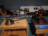
I built a mockup today [...] arm oscillates in vertical axis when touched.
Fantastic work thanks for photo and sharing ! Don't worry about VTF and arm oscillations when not in contact with a record - try it playing a record on a deck next and let us know how you get on.
indeed , you're right although the result is a bit counterintuitive.VTF increases as the stylus lifts because the magnets are further apart.
The implication is, riding warps even small ones will produce an increase in VTF. Also setting VTF MUST be done with the stylus at LP height if the scale is 0.5mm high or low VTF will off by 0.6g.
I put a level that has 0.5deg graduations on the arm and setting the arm level with this still produced variations in VTF of up to 0.3g with almost unnoticeable movement in the bubble. In a 9" arm 1mm height increase at the stylus is about 1/4 deg.
A while ago, I tried Eddy Current linear damping for air-bearing arms. But I couldn't tell that if the damping device worked or not. So, I gave it up. Actually, if I have something to test the damping results, it would be very nice. It might work since I don't have anything to measure the damping.
Fantastic work thanks for photo and sharing ! Don't worry about VTF and arm oscillations when not in contact with a record - try it playing a record on a deck next and let us know how you get on.
This arm is pretty crap and will not better than my current setup. I am building a new gimbal bearing arm that I can setup for both CW and mag-lev so I will be able to test both. Once I have it complete I'll do some testing and post the results.
My concern is - a tonearm MUST be stable and the mag-lev oscillates wildly when tapped and my current arm is very stable.
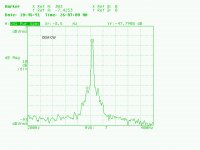
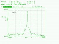
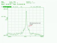
The plots are an EPA100 with OEM CW and my modified CW that locks to a new brass stub closer to the pivot, the 8.5Hz sidebands are almost gone, adding viscous damping improved this further
mag lev tonearm - YouTube
Attachments
eddy currents work either at high speeds or when using very powerful magnets and you don't really want moving powerful magnets around a phono system unless you can shield them ...A while ago, I tried Eddy Current linear damping for air-bearing arms. But I couldn't tell that if the damping device worked or not. So, I gave it up. Actually, if I have something to test the damping results, it would be very nice. It might work since I don't have anything to measure the damping.
This arm is pretty crap and will not better than my current setup. I am building a new gimbal bearing arm that I can setup for both CW and mag-lev so I will be able to test both. Once I have it complete I'll do some testing and post the results.
My concern is - a tonearm MUST be stable and the mag-lev oscillates wildly when tapped and my current arm is very stable.
mag lev tonearm - YouTube
Thanks for your video, fantastic efforts building a 'Mag-Lev' prototype, which you compare to a standard counterweighted arm set to near zero VTF and both arms are tested WITHOUT a cartridge suspension / stylus in contact with a record or other surface.
You bounce them both gently with your finger. The 'Mag-Lev' prototype bounces at circa 3hz with a very rapid decay – in under 1 second you can see a very rapid decrease in amplitude, and you can see the offset sinusoidal behaviour too, the beginning of the up stroke being faster than the beginning of the down stroke. Compared to the counterweighted arm which first bounces off hits the arm lift mechanism with nearly double the starting amplitude and still going at 50% after 5 second or longer all at a bit less than 1Hz all with relatively clean sinusoidal movements.
This is NOT the same as the resonance frequency behaviours of these arms playing a record damped by a cartridge suspension!
Upon what basis do you conclude a 3hz bounce in mid air is “pretty crap” compared to sub 1Hz mid air bounce in your “current setup” adjusted for no VTA?
To me your experiment shows the opposite of what you suggest, the mag-lev is very stable and your current arm oscillates wildly when tapped!
These two experiments highlight how different their geometry and mechanics are, and should be a warning not to jump to hasty conclusions. At least play a record with a 'Mag-Lev' before judgment day ;-)
Some suggestions (these are in some detail to also help new readers / experimenters get up to speed asap):-
1. Ensure the magnets are truly centred AND both are parallel (to the arm 'up-down' pivot). In the photo you uploaded it looks like you have epoxy bonded the magnets to the arm rear spigot and a bolt head in the mounting (bolted to the side to side pivot) you have constructed. I cannot see a lock nut on the bolt holding the top magnet? Any magnet mounting offsets a) torque / twist the bearings, and lower the magnetic repelling force. This link has lots of practical suggestion playing with repelling magnets.
Repelling Magnet Forces
2. Try different magnet strengths. As you can see from the graphs in this link, the closer the magnet surface are to each other, the more rapid magnetic repelling strength changes.
Such mid-air oscillation experiments allow us to tune a) the mid-air oscillation frequency and b) the range of change of VTF over distance from (a flat) record surface.
3. We can also tune this mid-air oscillation frequency by placing the magnet closer to the 'up-down' pivot. This will increase the lever ratio (spigot : arm wand) and for a given arm wand mass, the magnets will be physically closer, where magnetic repelling strength changes with distance are much more rapid. This is because magnetic attraction square law force falls off exponentially with linear increases in distance. With two magnets in opposition, a 2015 paper reports at very close distances "The magnetic dipole moment is determined from the slope of the magnetic force as a function of the inverse fourth power of the distance."
Magnetic force as a function of distance. | Download Scientific Diagram
However the kjmagnetics link above experimentally only confirms slightly less than square law.
4. Remove the arm spigot completely and mount the (pseudo) magnetic levitation assembly at 90 degrees facing upwards, directly above the gimbal bearing pivot planes. This is done to minimise changes in the direction of gravity on the tonearm's geometry / mass whilst it tracks inevitable record warps, thereby minimising oscillations in its moment of inertia. Check out Eric Vant's 2009 GB patent on this idea excellent idea.
GB2459273A - Magnetic tone arm balance mechanism
- Google Patents
Hope you are encouraged to continue your experiments and report your excellent work back here. Thanks.
The plots are an EPA100 with OEM CW and my modified CW that locks to a new brass stub closer to the pivot, the 8.5Hz sidebands are almost gone, adding viscous damping improved this further
Not sure what this is means? Please expand, thanks.
Please do not take any of my comments as negative. Magnetics is not an area I have any experience in, so this will be a steep learning curve.
The low vertical oscillation in the CW tonearm is less likely to be excited by warps than the higher fr of the mag-lev arm was my point. The measurement plots show how well the EPA100 performs.
I am planning to experiment further with mag-lev on the arm I currently building. I will build it so it can be swapped from CW to mag-lev for testing purposes. I read the patent and have already made a CAD drawing for the mods needed to mount the magnets above the pivot. I am not planning on active or coil this will be a passive magnet system only.
I have the equipment and technical background to measure the arm. Once I have the new arm complete I will test it and post the results. Should be a couple of weeks.
The plots are a Technics EPA100 tonearm. This tests the cartridge / tonearm, the 8.5Hz is an artifact caused by resonance/vibration in the arm/cartridge system.
The Technics CW with has a spring loaded magnet in a viscous bath inside the CW that is adjusted to the compliance of the cartridge to damp resonance. The plot shows how this does not work all that effectively.
The second plot is the arm with a new threaded brass stub and SS CW locked rigidly to the stub closer to the pivot.
Just this modification dropped the sidebands on the 1kHz tone. These sidebands are caused by amplitude modulation of the 1kHz by 8.5Hz.
The audibility of this was an increase in detail retrieval and spacial information.
Thanks! Your comments are all positive and have been stimulating my grey cells which is fun! Apparently human flight first 'took off' following heated 'debate' so we're in good company ")
Why disagreement is vital to advancing human understanding | Aeon Essays
And thanks for graph explanations too. Good to see confirmation of what we would expect from your counterweight modifications to the Technics EPA100 tonearm. Measurements indicate maximum actual performance of vinyl record replay is in the 60 to 70 dB range.
Comparison of analog and digital recording - Wikipedia
So the measured -48db drop to 60 Db at 8.5Hz in cartridge / tone arm artefact caused by resonance/vibration in the arm/cartridge system, ought to be audible as you report.
What cartridge compliance did you use for these resonance test graphs?
It would be interesting to see a range of compliances tested in your 'Mag-Lev' experimental rig. Perhaps the same range compared to a counterweighted arm's resonance behaviour too?
Really looking forward to seeing your test rig evolve, please keep us posted on your progress, thanks again!
eddy currents work either at high speeds or when using very powerful magnets and you don't really want moving powerful magnets around a phono system unless you can shield them ...
I tried a piece of N52 magnet, 10x5 mm round, over a piece of aluminum with slow speed. I could feel the drag force. In normal cases, damping may not be necessary only when the eccentricity causes the arm to accelerate, damping is needed. I also estimated the magnetic force at the cartridge since my tonearm is short. It was about 1 gauss.
The EPA100 test was with two cartridges a Stanton 881s compliance 30 x 10-6 dyne at 10Hz and Technics EPC205 12 x 10-6 @ 100Hz. The Stanton in theory should not be a good match for this arm.
Here is a thread I created to document the EPA, the first tests were done with the EPC205 all others were the 881s.
Technics EPA100 modifications
The aluminium arrived today for the bearing housing (we are locked down ATM) Hopefully I'll have a working prototype in a week. This is going to be a 4 point arm in a gimbal arrangement, NO bearings. I have to grind and polish the pins, so there is a lot of work.
Jim, Dynavector used eddy current damping on the DV505/7. I use viscous as it's easy to adjust a paddle in a bath to change damping.
When I added the viscous damping to the EPA100 I tested it with a signal analyseer and 315Hz and 1kHz tones, too much damping and the sidebands increased.
When I added the viscous damping to the EPA100 I tested it with a signal analyseer and 315Hz and 1kHz tones, too much damping and the sidebands increased.
Last edited:
I know it's off subject a little but here are the plots for my EPA100 with and without damping. If you switch betrween the plots you can clearly see the difference, these plots are with the EPC205
Attachments

- Home
- Source & Line
- Analogue Source
- Tone arm improvements - no counter-weight (pseudo) magnetic levitation