I could use some help solving an issue with the pitch control on a Technics SL-M1.
To start, the service manual I have for the SL-M1 doesn't show a pitch control or the associated circuit, which leads me to believe that this feature was added to later models. So I'm flying a little blind here.The circuit in the SL-M2 appears to be similar, so I'm basing what follows off of that.
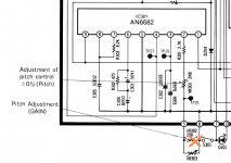
The issue is that I can't center the zero position on the pitch control. Per the service manual for the SL-M2, with the pitch slider (VR401) at zero and a frequency counter connected to test point TP27, you should adjust VR301 for between 262.075 kHz and 262.085 kHz. The closest I can come is 250.833 kHz, and that's with VR301 all the way clockwise (zero ohms). Of course, if I move the pitch slider from the physical center position, I can get the frequency dialed in correctly, but not until the slider is nearly all the way to the left.
This circuit is also similar to that of the Technics 1200 MK2, though neither the SL-M1 or SL-M2 have a pot for adjusting the pitch control gain like the 1200 does.
I've cleaned the fader with Deoxit F5, and it acts the same as before.
More data, FWIW:
IC301, pin 2: 1.9V
R301: 1.49k ohms
To start, the service manual I have for the SL-M1 doesn't show a pitch control or the associated circuit, which leads me to believe that this feature was added to later models. So I'm flying a little blind here.The circuit in the SL-M2 appears to be similar, so I'm basing what follows off of that.
The issue is that I can't center the zero position on the pitch control. Per the service manual for the SL-M2, with the pitch slider (VR401) at zero and a frequency counter connected to test point TP27, you should adjust VR301 for between 262.075 kHz and 262.085 kHz. The closest I can come is 250.833 kHz, and that's with VR301 all the way clockwise (zero ohms). Of course, if I move the pitch slider from the physical center position, I can get the frequency dialed in correctly, but not until the slider is nearly all the way to the left.
This circuit is also similar to that of the Technics 1200 MK2, though neither the SL-M1 or SL-M2 have a pot for adjusting the pitch control gain like the 1200 does.
I've cleaned the fader with Deoxit F5, and it acts the same as before.
More data, FWIW:
IC301, pin 2: 1.9V
R301: 1.49k ohms
Attachments
As ( I take it ) you don't have an oscilloscope as correct waveforms are shown then given the information you have provided either a change in value of the components around the Pitch control VR401 -which looks like the initial adjustment especially -C402 which should be changed or R301 on the marked "Pitch control Adjust" has changed value .
Both controls look in series with VR 301 being a preset .
Waveform has to be correct and your frequency counter might just show the major frequency even if the waveform is irregular due to faulty smoothing .
Check C301/302 as well.
Sorry missed your value on R301 looks very near correct value.
Both controls look in series with VR 301 being a preset .
Waveform has to be correct and your frequency counter might just show the major frequency even if the waveform is irregular due to faulty smoothing .
Check C301/302 as well.
Sorry missed your value on R301 looks very near correct value.
Last edited:
I checked the waveforms after my original post.
They all look correct, except for that of pin 7. Rather than a square wave, it appears very rounded off on one side. (Apologies for the poor photo.)

Also, how would one measure the waveform for pin 5, ground?
Re the rest, there is no C402 in the SL-M1. In fact, in the SL-M1 the pitch circuit board consists of only VR401, D401 (the LED to indicate the quartz lock is engaged), and S401 (to switch the quartz lock in and out). In this respect, it's more similar to the Technics 1200 MK2, minus the pitch gain pot.
They all look correct, except for that of pin 7. Rather than a square wave, it appears very rounded off on one side. (Apologies for the poor photo.)
Also, how would one measure the waveform for pin 5, ground?
Re the rest, there is no C402 in the SL-M1. In fact, in the SL-M1 the pitch circuit board consists of only VR401, D401 (the LED to indicate the quartz lock is engaged), and S401 (to switch the quartz lock in and out). In this respect, it's more similar to the Technics 1200 MK2, minus the pitch gain pot.
Attachments
Last edited:
On vinyl engine schematic there is no IC 401 but it says modifications can occur but if that should be a square wave then you have a timing circuit collapse .
Both positive & negative voltages look okay but you probably have a faulty capacitor in the timing circuit .
Your oscilloscope will be referenced to earth so putting the probe onto an earth shouldn't produce a waveform , at the most a bit of noise.
Maybe I am better looking up the 1200 MK2 schematic.
Not so easy there are many changes of internal electronics .
Yes, there's no IC301 in the SL-M1 schematic, or any other pitch control circuit parts shown. That's what makes this a challenge: It must have been added later in the production cycle. So we're left with the SL-M2 and 1200 MK2 as the best window into what's in the SL-M1. The square wave that's expected on pin 7 of IC301 can be seen here:

Yes definitely a timing issue ,as I said check out the capacitor values of the circuit associated with the production of the square wave timing.
Its a very long lists of variations of this deck , I will check the variations.
The M2 has the IC301 and the pitch control +pitch control adjust serried up and you are saying your turntable hasn't got IC 301 ?
Its a very long lists of variations of this deck , I will check the variations.
The M2 has the IC301 and the pitch control +pitch control adjust serried up and you are saying your turntable hasn't got IC 301 ?
Last edited:
The SL-M1 I'm working on has the IC301. I'm probably making this more confusing than it already is. The pitch circuits in the SL-M1 and SL-M2 are the same from IC301 up until connector CN401 on the pitch control board. At this point, the two models differ, with the SL-M1 (the one I'm working on) pitch board, consisting of just three things: the switch for quartz lock on/off, the LED, and the pitch slider itself.

I'll check those capacitors.
I'll check those capacitors.
Last edited:
So bringing the facts together - no C401 -right ,as its not shown in post # 3 ?
But VR303 connected connected in series with VR301 but one end of VR303 connected to earth at one end,yet in the later models M2 for instance C401 appears as well as in SL1200.
If true the simpler circuit didn't work out as well as they thought , notice though IC 401 is shown split into boxes for ease of tracing on those schematics showing it.
Right, no C401.
And agreed that the simpler circuit doesn't seem to have worked very well. But could it have been this bad when new? Because it's not that the pitch fader is just a little off speed when set to zero, but grossly so. This is why I've been trying to determine if something else has made this bad design worse. Perhaps the fader itself?
Some component measurements:
C305: 0.0013uF (Should be 0.0018uF)
C301: 0.015uf (Should be 0.015uF)
R302: 465 ohms (Should be 470 ohms)
R303: 8.25k ohms (Should be 8.2k ohms)
C304: 9.52uF 1.16 ESR (Should be 10uF)
C303: Need to test out of circuit still, but the ESR is showing as 2 ohms.
R301: 1.49k (Should be 1.5k)
What about C302 that's in parallel with C301 -0.033uF +C302-0.0068uF = (nearly ) 0.04uF as in post #3 ?
If that is okay then even though C305 isn't much out change it to =0.0018uF.
If still not right its either the chip is faulty or the feed to it is supplying the wrong signal.
If that is okay then even though C305 isn't much out change it to =0.0018uF.
If still not right its either the chip is faulty or the feed to it is supplying the wrong signal.
Did this ever get resolved? Fixable? I’m trying to buy a SL-M1 and have just been told it has this issue. Should i walk away from this or should I buy it anyway? I’m being told since the speed is quartz locked, i won’t need the manual pitch adjustment. My gut isn’t sure on this one so a response would be awesome. Thanks.
- Home
- Source & Line
- Analogue Source
- Technics SL-M1 pitch issue