I want to present a version of a pivoting tangential tracking tone arm. I will firstly describe the theoretical model without addressing the engineering implementation.
I have pored through the threads on DIY Audio concerned with related technology. I can’t find any projects with precisely the same viewpoint as put forward here but I may have missed some threads. To be absolutely clear, I won’t be discussing a parallel tracking tonearm, but a version of a pivoting tonearm that maintains tangency of stylus in the groove.The tonearm will experience no side thrust and hence will require no anti skating device.
The proposal will not rely on a pivoting cartridge headshell. Tangency can be enforced purely passively with no servo involved, although a servo version can be implemented.
I have tried to keep the principles close to fundamentals, so it can be clearly understood. In the interests of clarity I will present the proposals in a series of posts, each building on the previous, and illustrated with simple geometric diagrams.
I am not yet in a position to engage in detailed debate concerning the practical implementation. However I do welcome any constructive advice. In a later post I will show some videos of a basic working model.
A tangential tracking pivoting tonearm #2
I will assume the DIN maximum recorded LP radius as 14.605 cm and the minimum recorded radius as 5.75 cm. It will not matter if these values are replaced by other standards. The data can be easily changed.
The nominal effective tonearm length is deliberately given a small value, which would lead to excessive lateral tracking error in a conventional tonearm of the same length. The short length will moderate the effective mass in the interest of keeping the usual stylus compliance/effective mass resonant frequency in a desirable range.
For a straight, fixed headshell, zero offset, pivoting tonearm to maintain cartridge stylus tangency to the groove at each position, the tonearm effective (pivot to stylus) length must increase traversing from the outer groove to the inner groove while being allowed to pivot laterally and vertical.. In principle the tangency requirement can extend to the LP centre, but this is usually unnecessary.
Consider the coincident axes vertical and horizontal tonearm pivots located at a fixed location.
There is assumed to be a sliding contact bearing at the fixed pivots location. The tonearm is constrained to not rotate torsionally.
Since the tonearm extends in length over the pivots, there must be sufficient length of tonearm behind the pivot to allow it to extend fully while being supported at the fixed position pivots. For simplicity of illustration it is assumed the total length from front (stylus) to rear is exactly the distance from pivots to LP centre. Since the stylus will only be ending at the inner groove, the tonearm will never be fully extended and is always supported at the pivots.
The equations describing the tangency conditions require at most first year college maths. The coordinates of the paths of each end of the tonearm at tangency can be calculated and plotted exactly.
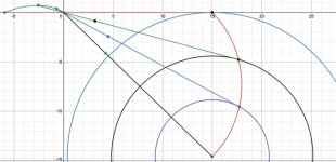
Assuming the sliding pivots location is fixed at the origin of the diagram below, the tonearm positions at 3 reference locations (outer groove, inner groove, mid-point groove) are indicated.
The effective tonearm length at the outer groove is 15 cm. The rear extension at this position is 5.936 cm, hence the total tonearm length is 20.936 cm. The effective tonearm length can be chosen to be different from 15 cm with little essential change to the description.
The path of the stylus across the LP is a portion of the circumference of the Thales semicircle, diameter the straight line from the tonearm pivots at the origin to the LP centre.
If the tonearm rear end is constrained to follow the required (blue) path and also slide through the origin over the fixed pivots, the stylus must follow the tangential (red) path.
The path of the tonearm rear end is not circular. However the 3 rear end points corresponding to the stylus at outer groove, inner groove and mid point, lie on a unique circle which approximates the rear end path very closely, in the groove playing area.
Also shown on the diagram below are the positions of the initial pivots location on the extended tonearm, at the 3 stylus reference positions. The distance from these points to the corresponding stylus end is always 15 cm.
I will assume the DIN maximum recorded LP radius as 14.605 cm and the minimum recorded radius as 5.75 cm. It will not matter if these values are replaced by other standards. The data can be easily changed.
The nominal effective tonearm length is deliberately given a small value, which would lead to excessive lateral tracking error in a conventional tonearm of the same length. The short length will moderate the effective mass in the interest of keeping the usual stylus compliance/effective mass resonant frequency in a desirable range.
For a straight, fixed headshell, zero offset, pivoting tonearm to maintain cartridge stylus tangency to the groove at each position, the tonearm effective (pivot to stylus) length must increase traversing from the outer groove to the inner groove while being allowed to pivot laterally and vertical.. In principle the tangency requirement can extend to the LP centre, but this is usually unnecessary.
Consider the coincident axes vertical and horizontal tonearm pivots located at a fixed location.
There is assumed to be a sliding contact bearing at the fixed pivots location. The tonearm is constrained to not rotate torsionally.
Since the tonearm extends in length over the pivots, there must be sufficient length of tonearm behind the pivot to allow it to extend fully while being supported at the fixed position pivots. For simplicity of illustration it is assumed the total length from front (stylus) to rear is exactly the distance from pivots to LP centre. Since the stylus will only be ending at the inner groove, the tonearm will never be fully extended and is always supported at the pivots.
The equations describing the tangency conditions require at most first year college maths. The coordinates of the paths of each end of the tonearm at tangency can be calculated and plotted exactly.
Assuming the sliding pivots location is fixed at the origin of the diagram below, the tonearm positions at 3 reference locations (outer groove, inner groove, mid-point groove) are indicated.
The effective tonearm length at the outer groove is 15 cm. The rear extension at this position is 5.936 cm, hence the total tonearm length is 20.936 cm. The effective tonearm length can be chosen to be different from 15 cm with little essential change to the description.
The path of the stylus across the LP is a portion of the circumference of the Thales semicircle, diameter the straight line from the tonearm pivots at the origin to the LP centre.
If the tonearm rear end is constrained to follow the required (blue) path and also slide through the origin over the fixed pivots, the stylus must follow the tangential (red) path.
The path of the tonearm rear end is not circular. However the 3 rear end points corresponding to the stylus at outer groove, inner groove and mid point, lie on a unique circle which approximates the rear end path very closely, in the groove playing area.
Also shown on the diagram below are the positions of the initial pivots location on the extended tonearm, at the 3 stylus reference positions. The distance from these points to the corresponding stylus end is always 15 cm.
Attachments
A tangential tracking pivoting tonearm #3
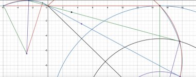
From my previous post, the three rear end tonearm positions corresponding to the stylus reference positions, outer, inner and mid-radius grooves, lie on a unique circle.
The centre of the circle and radius are easily found by chord bisection. Comparing the circle with the tangential tracking rear end path shows close agreement and exact coincidence at the 3 tonearm stylus reference positions. The corresponding stylus path for the circular rear end path is in extremely good agreement with the tangential path. The error is zero at the 3 reference points. Expanded plots of the tangential paths and the circular rear end versions are shown below with the tangential paths and circular paths shown overlaid.
If the tonearm rear followed the precise path (not circular), then the stylus would follow the exact tangential path (red circle). This could be achieved by a servo attached to the rear. However the additional complication over a passive linkage does not seem worthwhile for the additional accuracy. Especially considering the tolerances of cartridge cantilever alignment with the cartridge body or generator.
Attachments
A tangential tracking pivoting tonearm #4
From my previous post, when the tonearm rear end is constrained to follow the circular path as shown, the stylus path will follow closely the tangential path.
This is accomplished by a pivoting strut connecting the rear circle centre to the tonearm rear stub. The physical requirements are very low friction for all pivots and the sliding bearing at the tonearm pivot.
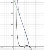
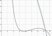
The calculated tonearm lateral angle referenced to the outer groove position, shows excellent agreement with the tangential tracking alignment. Below is the calculated tonearm angle (in degrees) as a function of the stylus radial distance from the LP centre. The tracking error over across the groove area is the difference between the two lateral angle plots. The plots show zero error at the inner, outer grooves and central grooves, a maximum error of approximately 0.75 degrees and tracking error less than 0.5 degrees over 50% of the groove radius. The zero crossings at the three reference radii are off by a few mm due to truncation and rounding errors in the graphical software. All the plots are implemented by inputting the complete algebraic expressions with no approximation, as is often the case for the tracking error analysis of conventional offset pivoted tonearms.
It is especially interesting that the tracking error at the inner grooves approaches zero, as this is where resolution is lost due to other well known factors.
Tangential tonearm angle (green), approximate tonearm angle (mauve), tracking angle error (black). Horizontal axis, stylus radial distance from centre.
From the tracking angle error plot, we should expect zero stylus side force at the three reference radii. In other words, they are equilibrium points.
From my previous post, when the tonearm rear end is constrained to follow the circular path as shown, the stylus path will follow closely the tangential path.
This is accomplished by a pivoting strut connecting the rear circle centre to the tonearm rear stub. The physical requirements are very low friction for all pivots and the sliding bearing at the tonearm pivot.
The calculated tonearm lateral angle referenced to the outer groove position, shows excellent agreement with the tangential tracking alignment. Below is the calculated tonearm angle (in degrees) as a function of the stylus radial distance from the LP centre. The tracking error over across the groove area is the difference between the two lateral angle plots. The plots show zero error at the inner, outer grooves and central grooves, a maximum error of approximately 0.75 degrees and tracking error less than 0.5 degrees over 50% of the groove radius. The zero crossings at the three reference radii are off by a few mm due to truncation and rounding errors in the graphical software. All the plots are implemented by inputting the complete algebraic expressions with no approximation, as is often the case for the tracking error analysis of conventional offset pivoted tonearms.
It is especially interesting that the tracking error at the inner grooves approaches zero, as this is where resolution is lost due to other well known factors.
Tangential tonearm angle (green), approximate tonearm angle (mauve), tracking angle error (black). Horizontal axis, stylus radial distance from centre.
From the tracking angle error plot, we should expect zero stylus side force at the three reference radii. In other words, they are equilibrium points.
Attachments
A tangential tracking pivoting tonearm #5
Below are two videos of a crude model of the tangential tracking pivoting tonearm.
The first video shows the stable tonearm position at any radius between outer and inner groove. The surface is a smooth rubber mat. The tonearm is nudged to simulate the tangential drag due to stylus/groove friction. What is important to note is that the axial bolt of the roller that replaces the role of a stylus, should point always directly at the centre spindle if tracking is tangential.
The second video shows that there is a real skating force when the tonearm is positioned away from the tangential position. This is only possible in the demonstration model due to the slop in the bearings which allow an off-track position. With a tonearm constructed with excellent precision linkage and bearings, off track positioning is impossible and tangential tracking is ensured.
Tangential tracking tonearm #3 - YouTube
Skating of tangential tracking tonearm - YouTube
That's a very interesting geometrical trick.
Your videos show in the absence of a groove how the tonearm will be pushed by positive or negative lateral forces until those forces reach equilibrium, or null, as the tonearm becomes tangential. In effect your tonearm/roller is behaving as a castor wheel, whilst the guiding mechanism ensures the length of the active part of the tonearm keeps the offset at or near zero.
However when playing a record the stylus is constrained to being in a groove and the lateral force to move the tonearm across the record surface to move the tonearm to a tangental position must be generated by the sideways displacement of the stylus/cantilever suspension.
This is the same as what happens to move a traditional pivoting tonearm, however in your proposed design the force required to move the active part of the tonearm will be magnified by a not inconsiderable factor by friction at the pivot point and the frictions in the guiding mechanism. I think this may cause the cantilever to be pushed significantly away from the center of the cartridge's linear region. With off centre, out of round and warped records these imperfections could easily modulate the output of the cartridge.
Also as the proportions of length of the active tonearm vary with position so the balance and tracking weight will vary, again by a not inconsiderable amount.
Have you thought about how to overcome those two derogatory consequences of the changing geometry of the proposed tonearm assembly?
That's a very interesting geometrical trick.
Your videos show in the absence of a groove how the tonearm will be pushed by positive or negative lateral forces until those forces reach equilibrium, or null, as the tonearm becomes tangential. In effect your tonearm/roller is behaving as a castor wheel, whilst the guiding mechanism ensures the length of the active part of the tonearm keeps the offset at or near zero.
However when playing a record the stylus is constrained to being in a groove and the lateral force to move the tonearm across the record surface to move the tonearm to a tangental position must be generated by the sideways displacement of the stylus/cantilever suspension.
This is the same as what happens to move a traditional pivoting tonearm, however in your proposed design the force required to move the active part of the tonearm will be magnified by a not inconsiderable factor by friction at the pivot point and the frictions in the guiding mechanism. I think this may cause the cantilever to be pushed significantly away from the center of the cartridge's linear region. With off centre, out of round and warped records these imperfections could easily modulate the output of the cartridge.
Also as the proportions of length of the active tonearm vary with position so the balance and tracking weight will vary, again by a not inconsiderable amount.
Have you thought about how to overcome those two derogatory consequences of the changing geometry of the proposed tonearm assembly?
Hi johnmath. Thanks for your comments. Firstly, I do recognise that for this proposal to work as required, all the linkage points, rotating bearings and sliding bearing, need to be of impeccable performance. My crude sliding "bearing" is nothing but a polyethylene carriage with minimal contact surfaces lubricated with PTFE. I am thinking that maybe an air bearing slider may give the required low friction. Fortunately, I have a fellow DIYer interested, who has experience with quality bearings required in tonearms, and parallel trackers.
The increase of tracking weight as the tonearm extends has been recognised and one idea that come to mind is a spring applied (inverse) tracking force that compensates for the varying extension. Any concern about the varying moving mass (inertia) is not so clear cut, since a rear counterweight will decrease inertia with tonearm extension, while the cartridge will increase inertia. There is probably an optimum combination of masses to keep the variation of inertia reasonably small.
As for your concerns as to how friction can drive the tonearm, it will have to wait until a more realistic model is constructed. The frictional force on the stylus will be real. This is what supplies the required minor inward motion. In the crude model of the videos, it is friction that is spinning the (cabinet sliding door) roller. I expect it will be sufficient to overcome bearing resistances.
Modulation effects of slip/stiction could be mitigated by some kind of fluid damping trough underneath the tonearm rear, where it is well aligned for this role.
Lots of unknowns. It will be fun.
The tonearm will experience no side thrust and hence will require no anti skating device.
Tangency can be enforced purely passively with no servo involved, although a servo version can be implemented.
It sounds like this is another pro-linear but anti-servo thread.
Below are two videos of a crude model of the tangential tracking pivoting tonearm.
Tangential tracking tonearm #3 - YouTube
Skating of tangential tracking tonearm - YouTube
If anything, the videos demonstrate that a passive implementation of the concept will not work. The arm motion does seem to maintain tangency as it is moved across the record surface, but it does so only because it is servo-controlled. Your hand is the servo, and your brain is the servo controller! In the first video, you tapped the butt of the arm to get it to extend and traverse tangentially. In the second video, You extended the length of the arm by hand to make it tangential at different spots on the record. If you actively (i.e., servo control) the frictional restraint of the ‘friction bearing’ to control the length of the arm so as to maintain tangency, that could work. The catch is that it would then no longer be a passive arm, and that would be contrary to the stated goal of this thread. Also, I believe that such servo control would be borrowing ideas from one or more of Straight Tracker’s patent(s).
As proof-of-concept, try adding enough weight on the cartridge end to increase the ‘stylus’ friction drag force to the point that it will overcome the inherent frictions in the model and see if the arm exhibits a tendency to self-align without skating.
The frictional force on the stylus will be real. This is what supplies the required minor inward motion. In the crude model of the videos, it is friction that is spinning the (cabinet sliding door) roller. I expect it will be sufficient to overcome bearing resistances.
Modulation effects of slip/stiction could be mitigated by some kind of fluid damping trough underneath the tonearm rear, where it is well aligned for this role.
The essential premise of your design concept is that the arm has to pivot on the forward-sliding friction point, and that there will be a self-correcting balance struck between the pivot frictional force needed to restrain the arm length to the correct geometric location, and the forward pointing stylus frictional drag force. There are contradictory requirements for what needs to happen at this pivot point. Ideally, arm pivot points/bearings would have no friction at all. On the other hand, you need some finite amount of friction to restrain the arm from extending itself out to full length. The balance between these two mutually exclusive requirements is crucial in order for the geometry to work, and it is your stated objective that this is to be accomplished passively without the use of servos. Good luck with that.
Ray K
You are correct. Although a servo version based on the same geometric ideas would be "perfect", this is not what I am looking for.It sounds like this is another pro-linear but anti-servo thread.
Not really. I could tap the rear end with my eyes closed, to the same effect. There is no feedback from my eyes/brain to influence the motion.Your hand is the servo, and your brain is the servo controller! In the first video, you tapped the butt of the arm to get it to extend and traverse tangentially.
As I stated, this extension to a non-tangential position is only possible because of the slop in the crude bearings. It is impossible for a precision version of the tonearm, which will only allow (nearly) tangential positions. It is meant to show how the side thrust arises off-track.In the second video, You extended the length of the arm by hand to make it tangential at different spots on the record.
If you actively (i.e., servo control) the frictional restraint of the ‘friction bearing’ to control the length of the arm so as to maintain tangency, that could work. The catch is that it would then no longer be a passive arm, and that would be contrary to the stated goal of this thread. Also, I believe that such servo control would be borrowing ideas from one or more of Straight Tracker’s patent(s).
Not interested in a servo version. If the passive idea is fundamentally flawed, I will abandon the concept. Discussion of cons is welcome.
I only added the "counterweight" to reduce the friction drag. I will remove it, which increases the downforce greatly. I will report back on the result.As proof-of-concept, try adding enough weight on the cartridge end to increase the ‘stylus’ friction drag force to the point that it will overcome the inherent frictions in the model and see if the arm exhibits a tendency to self-align without skating.
The essential premise of your design concept is that the arm has to pivot on the forward-sliding friction point, and that there will be a self-correcting balance struck between the pivot frictional force needed to restrain the arm length to the correct geometric location, and the forward pointing stylus frictional drag force. There are contradictory requirements for what needs to happen at this pivot point. Ideally, arm pivot points/bearings would have no friction at all. On the other hand, you need some finite amount of friction to restrain the arm from extending itself out to full length. The balance between these two mutually exclusive requirements is crucial in order for the geometry to work, and it is your stated objective that this is to be accomplished passively without the use of servos. Good luck with that.
Ray K
Friction is not the only force at play here. If you do a force analysis of the tonearm at equilibrium, there will be a stylus frictional force in the forward tonearm direction. Assume that the sliding pivot is frictionless, for the sake of demonstration, as are the rear strut pivots. There will be a reaction force at the rear tonearm pivot, with a component directed towards the rear (the strut will be in compression). This will oppose the stylus drag.
There will also be a reaction component at right angles to the tonearm rear. This will be in opposition to the horizontal reaction force at the frictionless sliding pivot.
active vs passive
I echo Ray's comment and question how the back pivot bar is struck by a deliberate force not considered a "servo" and how is this qualified as "passive"? Although a pivoting type of servo a la Reed 5T or Straight Tracker (Ralf) patented arm might be easier to implement instead of a 4 inch parallel slide, at least it will occupy less real estate. Instead of a backward pivot, a forward pivot only requires couple inches of servo curved path. At the end of the day, you are still moving or nudging it incrementally on a prescribed geometry with a deliberate force (your hand) and that is by definition a servo. And there's nothing wrong with it but it isn't passive.
I echo Ray's comment and question how the back pivot bar is struck by a deliberate force not considered a "servo" and how is this qualified as "passive"? Although a pivoting type of servo a la Reed 5T or Straight Tracker (Ralf) patented arm might be easier to implement instead of a 4 inch parallel slide, at least it will occupy less real estate. Instead of a backward pivot, a forward pivot only requires couple inches of servo curved path. At the end of the day, you are still moving or nudging it incrementally on a prescribed geometry with a deliberate force (your hand) and that is by definition a servo. And there's nothing wrong with it but it isn't passive.
At the end of the day, you are still moving or nudging it incrementally on a prescribed geometry with a deliberate force (your hand) and that is by definition a servo. And there's nothing wrong with it but it isn't passive.
The purpose of nudging in the original video was to simulate the effect forward stylus drag. My analysis indicates that the inward stylus force is zero at the outer, inner and central radii. Such being the case, in a perfect setting, there is little to none impetus to move the tonearm inward from the stationary position at the outer groove.
In the video below the counterweight is removed, increasing the downforce and frictional force. It can be seen that the roller takes a considerable time to start moving from the outer groove (equilibrium) radius. Then, because tangency is imperfect there is a minimal skating force that moves the tonearm inwards. However it attempts to re-establish tangency at each position until it approaches the inner groove equilibrium (tangency). The measured stopping radius agrees almost exactly with the inner groove radius (5.75 cm). I did up the speed from 33.33 rpm to 45 rpm mid-video to speed things up.
No nudging or servo required
")
YouTube
Thanks direct driverJust have to delete the word "studio" out of the link and you will see the video.
You posted a link to your Youtube Studio Edit page. Nobody else can see it.
Hope this works too
Tonearm #4 - YouTube
Thanks directdriver.You have made your case. I look forward to seeing further development with low friction bearings and proper set up. Best of luck to you!
My working model was shockingly effective. I will run the calculations again with a 25 cm effective initial tonearm length and post the results. This will allow a comparison with a typical 10"-12" traditional tonearm. I predict the maximum tracking error will decrease as well as the maximum tonearm extension. The tracking force variation and moment of inertia variation will decrease as percentages of the initial (unextended) values. Of course the initial unextended values will be greater. Watch this space.
I would like to see a video where the arm stays stationary in the beginning, middle, and end of record. In the last video I wish you could pick up the arm and place it in the middle to see if it stay still with no skating.
When your arm is finally operable you should do a timelapse video of the arm tracking an entire side of the vinyl disc, preferably with a tripod holding the camera! 😆
When your arm is finally operable you should do a timelapse video of the arm tracking an entire side of the vinyl disc, preferably with a tripod holding the camera! 😆
I must have missed this. Some threads are just too long to read everything. Are you referring to the Thiele tonearm?This is nearly exactly where I started.
The problem for me was any friction in the linear bearing will end up swamping the compliance of the cartridge, compounded by the torque component at the linear pivot.
I have a few ideas for a very low friction sliding bearing that I want to try. Not sure how the torque issue will arise, but I guess I will find out.
Are you referring to the Thiele tonearm?
No, my own implementation.

Not sure how the torque issue will arise
Your linear bearing has 2DOF, linear and rotation around the pivot, eccentricity will generate the torque around that pivot.
Good luck, always great to see people bashing at this problem.
- Home
- Source & Line
- Analogue Source
- A tangential tracking pivoting tonearm