A pulse count detector is the most linear of the FM discriminators but it has its own set of problems as can be seen on Kenwood, Akai, Nikko, Crown and Sansui tuners that used them. The detector will put out unwanted signal when tuning between stations. The problem is more evident on analog tuning where you have infinite tuning step.
Pulse count detectors need a very strong signal to work.
A ratio-detector can be made linear and produce THD < 0.005% at 75kHz deviation. I have state-of-art setup so I can routinely make these kind of measurements with FM stereo tuners.
PLL detectors with distortion cancellation works on paper. They deteriorates pretty quick in a a matter of seconds.
The Accuphase T-106 used the XOR method with a delay line. Their brochure clearly shows this. Haven’t tried it so no clue how good it is.
Pulse count detectors have poor S/N if used in a 10.7MHz IF. Multiple high end receivers and test gear in the 80's down-converted 10.7 MHz to 1 MHz to improve S/N.
The key to good FM demodulator performance is preferably flat or as a compromise, symmetrical group delay of the IF filters and a very linear demodulator.
There are numerous demodulator designs that can be made linear. In the old analog satellite world the audio subcarrier demodulators used very wide p-p deviations, higher than terrestrial FM, so we had to design demodulators that offered low distortion and good S/N. We used many different designs over the years, analog, PLL, digital..etc.
We also had "threshold extension" circuits like tracking filters preceding the demod that gave wide band IF filter designs similar S/N performance to narrow band IF designs.
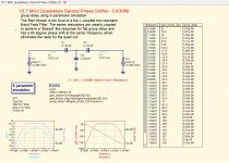
I published a Design Idea in the early 90's for a CA3089 based 10.7 MHz quadrature demodulator Phase Shift network. It had wider BW versus the standard "quad coil" circuit. Attached is a simulation done in QUCS.
I don't miss the days when the IF filters in commercial satellite and terrestrial point to point FM equipment required very complicated IF filters with group delay and amplitude equalizer sections. The group delay and amplitude of the IF filters had to be dead flat. Design of the filters took weeks. Every component and their parasitics needed to be measured at operating frequency for the CAD designs to work.
Attachments
Last edited:
This type of FM demodulator is perfectly linear, unlike the common tuned circuit solutions. I wonder what is the noise performance? Perhaps it needs another down conversion to 450 kHz to have acceptable S/N.
For terrestrial FM, it was common for high end receivers to down convert 10.7 MHZ to 1 MHZ to improve S/N.
Lots of great posts thanks everyone!
I majored in Communications Systems but never got to use it on the job so not
much hands on experience.
I remember reading an article in Audio on the "RIMO" IF filter from Richard
Modafferi and then looked up his original thesis:
http://archives.njit.edu/vol01/etd/1960s/1965/njit-etd1965-001/njit-etd1965-001.pdf
Made sense that you need linear phase in the IF with FM.
Last edited:
In any case, it's all been integrated and it's fun to play with Software Defined Radio like the cheap Adafruit USB RDS receiver. It was intended for European digital TV DVB decoding but it works fine for Stereo FM in North America, and much more if you add an appropriate antenna. This is a capture of some local FM band. Note the HD sidebands and the RDS text. I suppose the point is that a computer has become the head end for most everything.
I had heard about that Adafruit receiver but never looked into the details, might
take a look at it, thanks.
I remember reading an article in Audio on the "RIMO" IF filter from Richard
Modafferi and then looked up his original thesis:
http://archives.njit.edu/vol01/etd/1960s/1965/njit-etd1965-001/njit-etd1965-001.pdf
Made sense that you need linear phase in the IF with FM.
The 5 pole Butterworth in the design uses all top-coupled capacitors. This guarantees the Group Delay (GD) will not be symmetrical thus making equalization much more difficult. I realize it was designed a long time ago and he was a grad student and text books at the time were lacking and computer time expensive.
In the 80's one would alter the design of the filter to make the Group Delay symmetrical thus improving distortion without GD equalization or even better with GD equalization. The goal is to have the number of zeros at zero equal to number of zeros at infinity. You need both capacitive and inductive coupling.
A Butterworth will also have crappy selectivity so it is not a good choice for urban environments. High end receivers in the old days would have 2 IF sections, wide and narrow. Any "new" design will only use ceramic filters. They have sold linear phase ceramics for a long time.
In the old days you would have LC Bessel designs for the wide and ceramic for the narrow. A commercial design for the wide LC BPF might use a Chebyshev design with GD equalization. The narrow would be ceramic.
Back in the 80's and 90's people used to write a lot of RF SW in Basic. RF Design published an article for GD equalizer SW written in HP Basic. I converted it to Quick Basic and used it for many years to design GD equalizers for the Satellite industry.
Thers a reason for very few DIY tunners. DIY Rf gets scary for audio guys. Especially SOA FM tunners. Maybe if there built from a few large ICs, but going discrete would be a major undertaking. One look at the block diagram of my old (1977) tunner would scare most DIYers away. It still sounds great, buy the way.
https://fmtunerinfo.com/ST-9030block.gif
https://fmtunerinfo.com/ST-9030block.gif
10.7 MHz IF FM radios went out of fashion at least 15 years ago. A typical broadcast FM radio nowadays consists of an IC containing an LNA, I/Q mixer, pair of low-pass filters and sigma-delta ADCs and a lot of digital processing. Somewhat older FM radios consist of an almost completely analogue IC containing an LNA, an I/Q mixer mixing the signal to a low IF, an integrated complex bandpass filter, a quadrature demodulator using an integrated low-pass filter as the delay line and a stereo decoder and de-emphasis filters.
Getting off topic but here is the reference today:
http://www.accuphase.com/technical_information/t-1200_technical_informatione.pdf
http://www.accuphase.com/technical_information/t-1200_technical_informatione.pdf
When you type "Dirana3 YouTube" in duckduckgo.com, you will find a presentation about what is in the better car radios nowadays: pretty much the same as in the Accuphase tuner, but with fixed RF filters (because anything requiring manual adjustment is considered too expensive), with two front-ends each using a single I/Q conversion rather than a double conversion, with phased array techniques against multipath interference and with almost everything on a single chip.
Last edited:
yes I noticed the NXP line of chips way back when, they were(are?) amazing on paper at least. Not sure if still available. Certainly more powerful than Silicon Labs chips. DO you know any car head units that use them? They are very expensive chips so probably only in the TOTL models.
I'd be interested to know more details if you are willing to share.A ratio-detector can be made linear and produce THD < 0.005% at 75kHz deviation. I have state-of-art setup so I can routinely make these kind of measurements with FM stereo tuners.
I have a few Yamahs T-85's, they have a very good noise spec, esp in mono. maybe the thd is primarily the IF filters. I can't hear the difference anyways
")
Designed a Si4735 radio too, they are fun to work with. One experiment I would like to make is to compare the audio thd using the internal dac vs using an good external dac.
Another project is to construct a tuner using the obsolete Si4770 chip. Too bad it did not last long.
The THD = 0.005% is from a Sansui TU-9900 ratio detector output.
The TU-9900 detector board is fed with a 10.7MHz 75kHz deviation RF signal from a Panasonic VP-813xA FM stereo generator. The TU-9900 discriminator output is then analyzed with an Audio Precision System Two dual-domain audio analyzer using its FFT analyzer.
I have several of the Panasonic FM generators that I regularly check for FM linearity and residual noise using my HP 8901A modulation analyzer. I also have an HP 5210A FM discriminator and frequency meter that I used previously to check for FM linearity before I got the 8901A 11 years ago. I have to bring this up now as some folks in the past tend to question my test setup. My test equipment test results have been confirmed in the past by a metrology lab.
The excellent linearity of the discriminator and very linear phase wide IF section of the TU-9900 are its strength. The ancient MPX decoder is its weakness even though it uses a 1st generation PLL IC as its source for MPX decoder switching. The problem lies in the fact that the matrix switching it uses is not a perfect square wave. The MPX decoder will happily decode noise present +/-15kHz of the 2nd, 3rd, 4th and 5th harmonics of the 38kHz subcarrier. The same MPX decoder fault is present on all McIntosh FM stereo tuners from the MR-78 and older and the overpriced Marantz 20B and some of the 22xx receivers like the 2245.
Under perfect condition, the TU-9900 mono S/N unweighted 22kHz bandwidth is 83dB or better. With A-Weighting this goes up to 90dB. Stereo performance drop both numbers by 8-10dB mainly due to 60Hz and pilot leakage. With the North American FM situation of RDS, SCA and IBOC, the stereo S/N can drop to as low as 50dB in wide IF mode especially from stations with 3 IBOC streams with full digital sideband allocated power. Got to love how iBiquity and the US/Canadian regulators fudged their field testing numbers to qualify an inferior product which ended up messing majority of existing and future FM stereo tuners. Other than S/N degradation you can also get unwanted muting and disabling of stereo pilot detection from IBOC.
Bottom line is don’t go out and buy a TU-9900 just because you read here that its FM discriminator is very linear.
Finally going back to the original topic of pulse count detectors. Most commercial FM tuners that use this employ ceramic IF filters with little provision for group delay equalization so the resulting THD is much higher than it should.
Wouldn't a perfect square wave still convert noise around the 3rd harmonic of 38 kHz to the audio band? (The fifth should be suppressed by the IF filter.) Ideally you would want a perfect sine wave.
A perfect square wave will have odd harmonics and these end up decoding noise +/-15kHz of 114kHz and 190kHz respectively. That is a given for MPX decoder that use 50% square wave switching. You manipulate the duty cycle and reduce the 3rd harmonic to about -65dB like the Tandberg 3001A. You need narrow filters if you want to knock down noise +/-15kHz of 190kHz but this screws up FM discrimination and introduce unwanted distortion. The narrower an IF filter the less flat the group delay in the IF passband, too narrow and you clip the audio.
This notion of using perfect sine wave is hard to implement now. You need a perfect analog multiplier to accomplish this. Analog multiplier ICs are either too expensive, not that linear or limited dynamic range. The other method of using matched dual complimentary BJTs which are no longer made in quantity and cheap, e.g. from Isahaya makes it not feasible.
The more economical way is to use a post-detection filter and a low distortion MPX IC. I have my own custom IBOC LC filter and a lifetime supply of the usual MPX IC suspects. Better than 50dB stereo separation all the way to 15kHz is possible.
If anyone has a Yamaha T-85/TX-1000/TX-2000 which uses an analog multiplier for MPX decoder that they can sell or loan to me, I can test its immunity to RDS, SCA and IBOC. All in the name of science.
A good site re FM in general (including tuner descriptions and improvements) is from a diyA member and also lists optimized FM antennas.
88?108 MHz
Long ago my editor in chief made a deal with Pioneer so the F-90 chips were available for readers. Performance was good, especially stereo as the (square wave) output from the digital FM demodulator was used as switching signal for the locked 38 KHz carrier. Because of the high switching frequency, that stereo decoder was immune to the usual interference and the IF roll-off was enough. Distortion was listed as below 0.05% which still is a good value although the Sanyo LA3450 goes down to 0.005% (just bought a few on eBay). This is where a digital demodulator becomes important as for the DIY-er it provides very low THD without alignment etc. A feedback PLL might provide the best capture ratio (below 0.1 dB) but as a rule, VCO's aren't linear so the best of both worlds is to demodulate the VCO signal, digitally.
A perfect square wave will have odd harmonics and these end up decoding noise +/-15kHz of 114kHz and 190kHz respectively. That is a given for MPX decoder that use 50% square wave switching. You manipulate the duty cycle and reduce the 3rd harmonic to about -65dB like the Tandberg 3001A. You need narrow filters if you want to knock down noise +/-15kHz of 190kHz but this screws up FM discrimination and introduce unwanted distortion. The narrower an IF filter the less flat the group delay in the IF passband, too narrow and you clip the audio.
Assuming an IF bandwidth of 256 kHz or so (required bandwidth according to Carson's rule), the noise level of the multiplex signal should drop above 128 kHz. The 128 kHz is single-sided, that 256 kHz double-sided.
This notion of using perfect sine wave is hard to implement now. You need a perfect analog multiplier to accomplish this. Analog multiplier ICs are either too expensive, not that linear or limited dynamic range. The other method of using matched dual complimentary BJTs which are no longer made in quantity and cheap, e.g. from Isahaya makes it not feasible.
It's quite straightforward nowadays with digital IF signal processing, but you can also get pretty close with analogue electronics. It's the exact same issue as harmonic reject mixing: you can approximate a sine wave up to the n-th harmonic with a weighted sum of shifted square waves, with Walsh functions and in many other ways.
Assuming an IF bandwidth of 256 kHz or so (required bandwidth according to Carson's rule), the noise level of the multiplex signal should drop above 128 kHz. The 128 kHz is single-sided, that 256 kHz double-sided.
It's quite straightforward nowadays with digital IF signal processing, but you can also get pretty close with analogue electronics. It's the exact same issue as harmonic reject mixing: you can approximate a sine wave up to the n-th harmonic with a weighted sum of shifted square waves, with Walsh functions and in many other ways.
Can we go back to reality? You are talking about theories.
Do you have any measured data, snippets of code, logic and block diagrams, test bench and simulations of what you are talking about? If you do please share some of it. Send me an NDA and I will sign and honor it.
I personally have not invested any of my time with DSP techniques even though I’m capable of writing in C and VHDL. I used them in my previous job.
My posts about FM stereo tuners are mostly derived from the great deal of time I spent analyzing and actually working on them. I don’t make things up and I actually possess firsthand experience and knowledge of the posts I make. I know my limits.
- Status
- This old topic is closed. If you want to reopen this topic, contact a moderator using the "Report Post" button.
- Home
- Source & Line
- Analogue Source
- FM Discriminator With XOR Gate