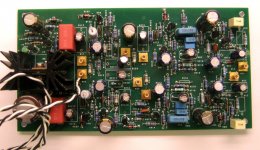
Attached is a picture of a new project combining 2 channels of RIAA preamp plus line stage on a single PCB. The RIAA stage is passively equalized, and is based on a simple bipolar 2-transistor gain cell w/feedback boasting impressively low simulated THD. The line amp uses a beefed-up version of the same 2-transistor gain cell with a gain of 5X. The board is all stuffed and ready for power-up and characterization. The board also incorporates a discrete shunt regulator that takes a +40V or so input voltage and generates a +30V regulated output to power all stages.
Attachments
Last edited:
The 2-transistor gain cell I'm using has a long history = Marshall Leach used a variant in a preamp project presented in Audio magazine back in the 70's.
https://leachlegacy.ece.gatech.edu/papers/wbpreamp/feb77article.pdf
A review of a Crown product back in the 70's (also in Audio magazine) praised the clarity of an RIAA amplifier using a 2-transistor complementary gain cell.
I started looking at variants of the gain cell in threads like these:
"Firefly" Unity Gain Buffer
JLH Liniac Revisited
All-In-One Preamp Circuit
A lot of these circuits used jfets and mosfets rather than bipolar devices. This particular project was launched to pare the component count to a minimum for good functionality. I toyed with the idea of using current source loading for the input transistor of the gain cell - this reduced THD, but only the 2nd harmonic, so that the 2nd harmonic and odd-order products were equal in amplitude, albeit low. I like to see a harmonic spectrum with 2nd order being the dominant product, with odd-order products substantiall down compared with 2nd order, as well as deceasing amplitude as a function of harmonic order.
Last edited:
The board shown in the initial post consists of a passively equalized RIAA preamp with an input gain block of 40X , the passive EQ network, followed by a 30X gain block (40 dB gain at 1 kHz). The line amp section has a gain of 5X.
Attached is the schematic of the input 40X gain cell with simulated THD.
Attached is the schematic of the input 40X gain cell with simulated THD.
Attachments
As can be seen, the basic gain cells used in this amp are extremely simple, but with surprisingly good performance for such a simple circuit. Actual devices used are the Fairchild/On Semi KSC1845 and the Fairchild/On Semi MPSW63. The MPSW63 was chosen because it is in a TO-92L package with extra power dissipation capability, necessary for the line amplifier block, as it runs with a lot of bias current.
There’s a very nice discussion on the JFET approach in The AoE ‘X Files’
Can you give me a reference to this, Bonsai?
(I googled The AoE ‘X Files’ but only got hits for the TV series.
 )
)Andy
The Art of Electronics ‘X Files’
Art of Electronics – The X Chapters | by Horowitz and Hill
Art of Electronics – The X Chapters | by Horowitz and Hill
I've messed extensively with an n-channel jfet + p-channel mosfet incarnation of this gain cell. The results are currently sitting in my living room being fed by a Denon DP-1000 turntable with Audio Technica AT440MLB cartridge. The objective was a preamp that could satisfy the fiddly capacitive loading requirements of the AT MM cartridges, and the preamp succeeded in that respect - the result is very listenable.
This bipolar effort was an attempt to gin up a preamp where one could just drop the components into the board and go without tedious matching of jfets. One disadvantage of the bipolar approach is that you need a fairly large blocking/coupling capacitor at the input to isolate the first stage biasing from the cartridge. This cap needs to be either an electrolytic or a mondo film cap - the film cap would be physically huge and as a result, would be an avenue for spurious noise pickup.
So, I'm not entirely happy with the approach I've presented here, though the simulation results are very presentable. Listening will tell the tale.
One of the threads I cited earlier describes the process of designing various mix-and-match gain blocks for use in an all-in-one preamp board. Here's that thread again. Various approaches explored included complementary feedback pairs, folded cascode stages, and simulated SIT/triode lineamp stages.
All-In-One Preamp Circuit
Last edited:
OK, simulations are one thing, but the actual circuit is the real deal.
This means, in plain English, that the bias network for the real circuit may not match that of he simulation. Here's the current schematic for the RIAA section of the preamp. I sat down on the bench with the board this afternoon and adjusted bias network values for proper output centering. The schematic shown here includes values that actually work.
This means, in plain English, that the bias network for the real circuit may not match that of he simulation. Here's the current schematic for the RIAA section of the preamp. I sat down on the bench with the board this afternoon and adjusted bias network values for proper output centering. The schematic shown here includes values that actually work.
Attachments
Last edited:
The MPSW63 is still available NOS. If I actually decide to carry on with this design (depends on actual test and listening), I may decide to offer a kit.
Another possibility is going the surface mount route with a SOT223 part like FZT/PZTA64.
I may lay out a board to accept both the through-hole and surface mount Darlington parts.
This, however, is based on the assumption that the project is actually listenable. All this work was done on a lark to see what it would actually take to make a decent quality single supply AIO board using only bipolar parts. I already have a jfet/mosfet setup in my living room giving very listenable results using the AT440MLB, a cartridge that has very fiddly capacitive loading requirements.
...values of R30 and R31 ....
R30A and R30B are different values.
- Home
- Source & Line
- Analogue Source
- Bipolar AIO RIAA + Lineamp