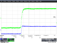
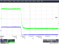
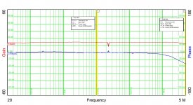
I ran gain-phase scans on the RIAA section this afternoon, and the two channels were well-matched. I tried running the line stages, but got wonky results, probably due to a medium level brain fart. I'll try again next weekend...
Attachments
I had to sweat some blood this afternoon to get the 2nd channel of the line amplifier working. It appears there was an internal hairline short to ground on the output trace. I isolated the defective trace with a couple of Dremel cuts, and will be running a separate lead to hook up the output SMB connector. First defective board I've encountered from PCBWAY... I'll be checking the other boards from that batch, but I'd be wiling to bet that this particular board was a fluke.
Attachments
Last edited:
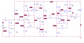
I have another layout going that fixes issues with the current one and adds a few other needed touches. One thing I might add is some RF filtering to both the RIAA and line amp inputs, since they are too fast for their own good. I may also adjust compensation to slow things down a bit. The layout also adds the surface mount SOT-223 option for the output Darlington in each gain cell, specifically the FZT/PZTA64.
I had a DJ mixer that would pick up transmissions from taxis (back when they still had 2-way radios). I'd like to avoid that here...
I had a DJ mixer that would pick up transmissions from taxis (back when they still had 2-way radios). I'd like to avoid that here...
Last edited:
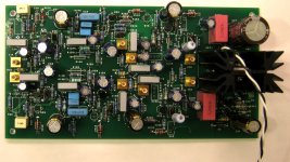
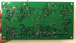
Front and back pictures of the Rev2 board. I chose to populate the back side SMT Darlingtons (FZTA64) to see if there was sufficient copper area for heat sinking. This is especially important with the line amp, which runs with a lot of Class A bias.
Attachments
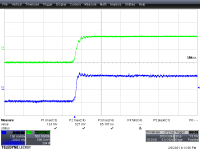
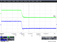
I'm finally going to fire up the finished preamp for some characterization by the gain-phase analyzer over the weekend. One thing I might consider doing is to use a 2nd transistor thermally coupled to the input transistor on each gain block for bias thermal compensation, rather than the separate diode currently used.
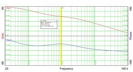
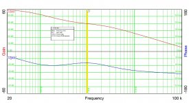
I got results on the gain-phase analyzer that did not look like the standard RIAA curve. This is puzzling, as both gain blocks check out fine in simulation. I'll be looking into the values for the passive filter - a bit non-standard, as I'm using a 100k resistor to bias the 2nd stage, so the first 2 resistors feeding the passive filter need to accommodate this. More later....
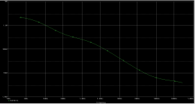
One thing I note is that your input stages biasing is sensitive to hfe, I'd check the Q1A/B have the expected base voltage and is actually working in the active region.I got results on the gain-phase analyzer that did not look like the standard RIAA curve. This is puzzling, as both gain blocks check out fine in simulation. I'll be looking into the values for the passive filter - a bit non-standard, as I'm using a 100k resistor to bias the 2nd stage, so the first 2 resistors feeding the passive filter need to accommodate this. More later....
And no decoupling across the zeners D3/D6 worries me - zeners can be extremely noisy. Perhaps a pair of series LEDs might be worth considering.
I have laid out a new board utilizing split feedback-based RIAA EQ, with pots to set the bias levels on the RIAA and line gain blocks. I may change these for a 2-pin header to be able to plug in a pot to set a fixed resistor for bias. I'm also using diode-connected transistors thermally coupled to each input transistor for bias stabilization. Instead of using zeners for level shifting in the Darlington output stage, I'm using two series GaAsP red LEDs. The boards have just finished fab in Shenzen, and I should be getting them in a few days. The split EQ scheme simulates nicely - I'd like to see similar behavior for the actual circuit.
- Home
- Source & Line
- Analogue Source
- Bipolar AIO RIAA + Lineamp