Yes, for the display, but it already has a button on pin_A0 for start/stop (short press) and 33/45 (long press), this will be maintained.It will use only the phone app for display? I was hoping to make a version that could be setup using the phone app but then started and stopped via separate switch so I don't have to find my phone every time. Since retiring I am not diligent about keeping the phone with me...
I've got the interface updated now, about to get tested in system......
Update with tachometer function included
This now accepts input from a sensor to measure and display current speed in rpm, along with a pulse generator for 30rpm which can be looped in for testing. The default pins for these are:
#define PIN_TACH 12
#define PIN_GEN 10
There are a couple of user configurable items for the tachometer:
#define CP_REV 2
- the number of pulses per rev
#define NR_AVG 4
- the number of pulses over which to perform a weighted average
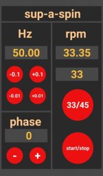
The Bluetooth interface has been updated to show measured speed above the selected speed, see picture of unit in operation.
The new Arduino code is attached.
- Rich
This now accepts input from a sensor to measure and display current speed in rpm, along with a pulse generator for 30rpm which can be looped in for testing. The default pins for these are:
#define PIN_TACH 12
#define PIN_GEN 10
There are a couple of user configurable items for the tachometer:
#define CP_REV 2
- the number of pulses per rev
#define NR_AVG 4
- the number of pulses over which to perform a weighted average
The Bluetooth interface has been updated to show measured speed above the selected speed, see picture of unit in operation.
The new Arduino code is attached.
- Rich
Attachments
Last edited:
thanks for yor sharing,still some question here.
1. what purpose of the 10 PIN? and how to connect it with Arduion?
#define PIN_GEN 10
There are a couple of user configurable items for the tachometer:
#define CP_REV 2
- the number of pulses per rev
#define NR_AVG 4
Not fully under the NR_AVG define as 4
Sorry lots of questions.
1. what purpose of the 10 PIN? and how to connect it with Arduion?
#define PIN_GEN 10
There are a couple of user configurable items for the tachometer:
#define CP_REV 2
- the number of pulses per rev
#define NR_AVG 4
Not fully under the NR_AVG define as 4
Sorry lots of questions.
Last edited:
Thanks, looking forward to you getting the hardware up and running, any feedback welcome.It works like a charm!
No problem!thanks for yor sharing,still some question here.
1. what purpose of the 10 PIN? and how to connect it with Arduion?
#define PIN_GEN 10
There are a couple of user configurable items for the tachometer:
#define CP_REV 2
- the number of pulses per rev
#define NR_AVG 4
Not fully under the NR_AVG define as 4
Sorry lots of questions.
PIN_GEN generates a square wave to emulate a turntable running at 30rpm, so can be connected directly to PIN_TACH to check the tachometer operation without using a sensor just in case that's useful for debugging your setup (It was more useful for me developing the firmware so I didn't have to have a turntable nearby!)
In fact there's an oversight in the code, I don't take account of CP_REV in the square wave generation, so really the line:
OCR1A = 0x7A11; // for 30rpm
should be
OCR1A = 0xF424 / CP_REV; // for 30rpm
NR_AVG is the number of readings over which a weighted averaging of the tachometer measurements is performed, with the highest weighting for the most recent one. Feel free to adjust this for what suits you and your setup, it works from 1 (no averaging) upwards.
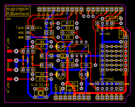
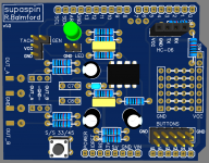
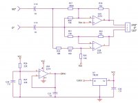
I have dived into EasyEDA to produce a more complete schematic, included below, and also have an Arduino shield PCB design on the way. There are provisions for conecting the output via 3.5mm jack, screw terminal block, or solder pads, and the HC-06 module can be socketed as shown, or permanently mounted underneath the board with power switch to allow programming. Any comments welcome
Attachments
Sure, I'm finalising a board for another project, then I'll get this one made and tested out, and all being well I'll have a few spare I can supply, and share the Gerber too.This is excellent. Much easier than using blank protoshield. Id be interested in either a pcb or the Gerbers.
Here's the updated PCB with an option for extra output filtering and a prototype area for mods if required.
Attachments
boards ready!
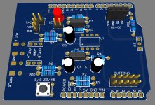
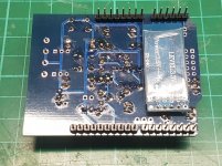
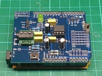
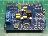
Received the boards and made one up, the photos below show a version with screw terminal outputs, another with a 3.5mm stereo socket (mounted on the Arduino), plus an underside view with the Bluetooth module mounted.
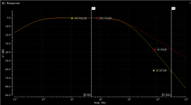
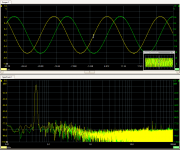
The additional filtering on the output gives good attenuation of the PWM harmonics, with only a tiny additional attenuation in the pass-band, with the simulated AC response with and without the additional filter shown below. The sinewave outputs and spectrum are shown in the next picture.
Also included here are the updated schematic and Arduino code, please see the first post for details of uploading and runnin for the first time.
If anyone wants to make one up, I have some spare boards that I'm happy to send out at cost ($1.50) + postage, or the Gerbers are attached here also.
- Rich
Received the boards and made one up, the photos below show a version with screw terminal outputs, another with a 3.5mm stereo socket (mounted on the Arduino), plus an underside view with the Bluetooth module mounted.
The additional filtering on the output gives good attenuation of the PWM harmonics, with only a tiny additional attenuation in the pass-band, with the simulated AC response with and without the additional filter shown below. The sinewave outputs and spectrum are shown in the next picture.
Also included here are the updated schematic and Arduino code, please see the first post for details of uploading and runnin for the first time.
If anyone wants to make one up, I have some spare boards that I'm happy to send out at cost ($1.50) + postage, or the Gerbers are attached here also.
- Rich
Attachments
Last edited by a moderator:
Great, yes please do.Yes, I would like one. Ill send a PM.
If you can send in France, me too.
Thanks, both your boards are ready to postI would like one, this looks like a great project.
It would be quite straightforward to take the two anti-phase outputs and feed them through a phase splitter to create a 3 phase output that could then be fed into the MA3D.
This was discussed a few years ago, before Bill (Phoenix) brought out the SG4.
Here's an example of the 2 to 3 phase splitter
This was discussed a few years ago, before Bill (Phoenix) brought out the SG4.
Here's an example of the 2 to 3 phase splitter
Attachments
Nice project !
The board is designed to work with 2 phase synchronous motors only. Is it possible to stack two pcb to drive a 3 phase BLDC motor (with the MA-3D board) ?
'Interesting' question!I had the same question: what would be involved to make a 3 phase version?
The Atmel microcontroller has (only) 2 hardware PWM output for each timer/counter, hence it was straightforward to generate 2 phases with a fixed relationship. Going to 3 phases would require using a second timer/counter, which should be possible if the additional calculations can be squeezed into the time available for the interrupt service routine. I'd probably have to ditch the tachometer test tone generator to liberate its timer. Hardware wise, I'm sure a second board could be stacked and connected to run from an alternative output pin. The extra hardware solution shown above is an option, but I think it would be nice to do it in the processor if possible. I have some other projects on the go (and a job unfortunately!), but you never know what may happen on a rainy day.......
Last edited:
- Home
- Source & Line
- Analogue Source
- 2 phase synthesised sinewave generator for synchronous motor drive