Hi hirrscwi, sorry it was overnight here in the UK! I think you've realised the two issues: firstly, as the HC-06 shares the hardware serial interface with the programming interface, it needs to be disconnected/powered off in order to program the Arduino; secondly, the baud rate will need to match your particular module, as seen in this line of the code
#define REMOTEXY_SERIAL_SPEED 19200
Either this, or the baud rate of your module, can be changed so that they both match.
(I've added this information into the first post, thanks for highlighting it)
Glad you're making progress")
#define REMOTEXY_SERIAL_SPEED 19200
Either this, or the baud rate of your module, can be changed so that they both match.
(I've added this information into the first post, thanks for highlighting it)
Glad you're making progress
Last edited:
Yes, it is possible to change the baud rate of the HC-06.
Here are the commands :
"
For HC06: On arduino serial monitor type "AT" (without the quotes) and press enter, "OK" will confirm AT mode. Unlike HC05, you can't see the default name or baud rate. You can only change them. To change name type AT+NAMEDESIRED NAME, notice that there should be no space between the command and name. The module will reply OKyour set name. For example, AT+NAMEPROTOTYPE will set the name to PROTOTYPE. To change baud rate, type AT+BAUDX, where X=1 to 9.
1 set to 1200bps
2 set to 2400bps
3 set to 4800bps
4 set to 9600bps (Default)
5 set to 19200bps
6 set to 38400bps
7 set to 57600bps
8 set to 115200bps
so sending AT+BAUD4 will set the baud rate to 9600.
For Tera Term write down the commands somewhere else and paste it on the console by right clicking. No need of pressing enter. The command will be executed immediately and confirmedHC 06 AT commands are limited, all I could find are given here.
HC 06 AT commands are limited, all I could find are given here.
AT : check the connection
AT+NAME: Change name. No space between name and command.
AT+BAUD: change baud rate, x is baud rate code, no space between command and code.
AT+PIN: change pin, xxxx is the pin, again, no space.
AT+VERSION
"
I've been trying a couple options until receiving the parts for the filter. I have been trying to include a sketch developed here on DIYAudio for an Arduino based turntable tachometer. But both sketches use Timer2. Would it be difficult to change this sketch to use one of the other timers? If so, some guidance would be appreciated.
Hi hirscwi,
Perhaps another MCU could help? I believe this board is supported by the Arduino framework. Else, seach blue-pill board.
https://www.mouser.dk/ProductDetail/STMicroelectronics/NUCLEO-L432KC/?qs=qzCNEk%252BRr%252BajjPvxjwWK5g%3D%3D
The processor is of course over-kill but it's cheap and available. And this is after all DIY so a littlebit of over-kill is expected
Mogens
Yes definitely possible. I try to use Timer2 or Timer1 in preference to Timer0 as the latter is used for the millis() and delay() functions which can be handy.I've been trying a couple options until receiving the parts for the filter. I have been trying to include a sketch developed here on DIYAudio for an Arduino based turntable tachometer. But both sketches use Timer2. Would it be difficult to change this sketch to use one of the other timers? If so, some guidance would be appreciated.
I've just had a look at the ATmega328P datasheet and Timer1 does have an 8-bit phase corect PWM mode, so I'll do the experiment and let you know the changes required. The output pins would move from 3,11 to 9,10, so worth deciding before finalising the hardware.
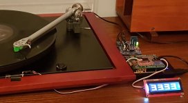
I've also developed a tachometer running on a separate Arduino (see picture for both in operation), and use Timer1 for that as it is 16-bit and hence easier for measuring the longish intervals of a turntable platter. So another option would be to use Timer1 for the tachometer.
I was thinking of ultimately linking up them both to allow closed-loop speed control, I haven't experimentd with integrating both functions into a single Arduino, although that would potentially make this more convenient.
Attachments
Last edited:
OK, to move from Timer2 to Timer 1, change:
#define PIN_PWMa 11 // OC2A Timer2
#define PIN_PWMb 3 // OC2B Timer2
#define PIN_LED 9
to
#define PIN_PWMa 9 // OC1A Timer1
#define PIN_PWMb 10 // OC1B Timer1
#define PIN_LED 8
(note the LED also needs moving from pin 9 as this is now needed for the PWM)
ISR(TIMER2_OVF_vect) {
to
ISR(TIMER1_OVF_vect) {
OCR2A = readA;
OCR2B = readB;
to
OCR1A = readA;
OCR1B = readB;
TIMSK2 |= (1<<TOIE2); // enable Timer2 Interrupt
to
TIMSK1 |= (1<<TOIE1); // enable Timer1 Interrupt
TIMSK2 &= ~(1<<TOIE2); // disable Timer2 Interrupt
OCR2A = pgm_read_byte(&sinewave_data[0]);
OCR2B = OCR2A;
to
TIMSK1 &= ~(1<<TOIE1); // disable Timer1 Interrupt
OCR1A = pgm_read_byte(&sinewave_data[0]);
OCR1B = OCR1A;
TCCR2A = (1<<COM2A1) | (1<<COM2B1); // clear on Compare Match
TCCR2A |= (1<<WGM20); // PWM phase correct
TCCR2B = (1<<CS20); // no prescaling
to
TCCR1A = (1<<COM1A1) | (1<<COM1B1); // clear on Compare Match
TCCR1A |= (1<<WGM10); // PWM phase correct 8-bit
TCCR1B = (1<<CS10); // no prescaling
I think that's it!
Last edited:
I think it will be a problem to use 2 separate timers to do the tach and DDS generation. The ATMega328 has only one interrupt priority, so when it services one interrupt, all others are blocked until it is done. This can seriously impact the timing of either operation. On the tach sketch that I wrote, I disabled Timer0 and Timer1 to prevent them from interfering with timer2 counts for the tach.
Since the DDS interrupt is running at 31,372.55 Hz, it could also be used to process the tach count, as long as you can complete both tasks within 510 instruction cycles. The constant CALIBRATE will need to be adjusted to 60*clock or 1,882,353 instead of 1.875M.
Since the DDS interrupt is running at 31,372.55 Hz, it could also be used to process the tach count, as long as you can complete both tasks within 510 instruction cycles. The constant CALIBRATE will need to be adjusted to 60*clock or 1,882,353 instead of 1.875M.
Yeah my initial thought too was that interrupt priorities could be an issue, as the tachometer would typically use a pin change interrupt to monitor the platter sensor.
I just had a look, the PWM Interrupt Service Routine (ISR) takes ~20us of the ~32us cycle time, so not a lot left for the tachometer filtering and display processing, plus the simple control loop when integrating the two systems, although this shouldn't be a problem at the very low update rate required.
Communicating between two stand-alone Arduino's shouldn't be a problem either, so I may well still go down this route someday, then I'd have a fully modular/flexible system.
I've found using the other timers in the tachometer was not a problem though, I use one of the other timers to generate a pulse which can be looped into the sensor input for testing, and the third (via the millis() function) for a watchdog timer to determine when the platter had stopped.
Thanks, Pyramid. I was wondering if 2 interrupts would cause a problem but am not knowledgeable enough to determine that.
Yes, I was trying to integrate the tach program that you wrote.
I noticed that Timer0 was disabled but didn't see that Timer1 was disabled also.
So, to implement your suggestion, do I just move the ISR from the tach program into the ISR doing the DDS generation?
Yes, I was trying to integrate the tach program that you wrote.
I noticed that Timer0 was disabled but didn't see that Timer1 was disabled also.
So, to implement your suggestion, do I just move the ISR from the tach program into the ISR doing the DDS generation?
I noticed that Timer0 was disabled but didn't see that Timer1 was disabled also.
It's been awhile since I looked at it; Timer1 wasn't in use, so I probably didn't disable it. As Rich said, the Arduino OS uses Timer0 for millis(), so I disabled it and incorporated my own millisecond delay routine in Timer2.
So, to implement your suggestion, do I just move the ISR from the tach program into the ISR doing the DDS generation?
That's the idea, but you have to make sure that both operations get completed within 32µSec or the next interrupt won't occur on time and the main code will never get executed. The tach ISR I wrote toggled a bit that was used for calibration. I would disable that function and possibly the delay routine I added to save instruction cycles.
Going with the 20bit phase accumulator might shave off enough cycles as well as there was less math involved.
This is actually easier to figure out in assembly language as the code is tighter (runs faster) and you can compute exactly how many cycles are consumed. If the Arduino compiler handles assembly language, you might go that route instead.
Good luck.
DIY member Scobham did an implementation here:
Turntable Tachometer and motor speed controller
Last edited:
Yeah my initial thought too was that interrupt priorities could be an issue, as the tachometer would typically use a pin change interrupt to monitor the platter sensor.
The tach sketch I did a couple years ago did not use an external pin interrupt, just timer2 running at 32.000µS. It looked at the external pin for a negative edge, and captured a 32 bit count when that happened and cleared the counter for the next trigger.
Your DDS interrupt is running at 31.875µS, so it should work (just have to change the constant CALIBRATE) as long as you can get everything done in under 32 µS.
OK, yes I don't think getting the PWM and tachometer to run concurrently as you suggest would be a problem, and the 'slack' time in each PWM frame should be plenty for the 'background' processing of the tachometer calculation and display, and buttons.The tach sketch I did a couple years ago did not use an external pin interrupt, just timer2 running at 32.000µS. It looked at the external pin for a negative edge, and captured a 32 bit count when that happened and cleared the counter for the next trigger.
Your DDS interrupt is running at 31.875µS, so it should work (just have to change the constant CALIBRATE) as long as you can get everything done in under 32 µS.
However, combining my designs as they currently are, although I'd be using the hardware serial for the Bluetooth tuning interface, the serial interface for the display I'm using is using a software serial interface, which will have it's own implications on the other interrupts, so that would require some thinking about. Just when I thought I'd 'finished'
Last edited:
I've managed to add the tachometer function running on the PWM interrupt as described by Pyramid, seems to work well. I've had to ditch the LCD display I was using for the tacho, so will add it into the Bluetooth/App interface. Once done and tidied up I'll post some new code for you to try
It will use only the phone app for display? I was hoping to make a version that could be setup using the phone app but then started and stopped via separate switch so I don't have to find my phone every time. Since retiring I am not diligent about keeping the phone with me...
- Home
- Source & Line
- Analogue Source
- 2 phase synthesised sinewave generator for synchronous motor drive