Dear members,
I have recently acquired a fantastic sounding prepreamplifier from way back in the eighties; Electrocompaniet MC-2. An all class A device originally marketed as having a self-sensing system for detecting optimal load on cartridge based on current flow.
The idea was said to improve headroom and dynamics. The load and feedback was set through resistors (using dip-switches).
My unit is a later one with exchangeable resistors for optimising load and gain. My problem is, I simply do not understand how it works!
Ideally I want to be able to adjust MC-2 to any chosen cartridge. But how....?
I hope the community is able to shed some light on this")
How is the load resistor correlated to the gain resistor?
Do the cartridge only see the load resistor value or is some of the circuit part of the total load seen by cartridge?
How to calculate and adjust gain using feedback resistor? I guess the feedback resistor value is dependant on the load resistor, but otherwise I have no clue.
I found a drawn schematics on the internet which correlates well with my unit except for trim resistor setup for feedback/gain. I have only a fixed resistor in mine.
This is for the first version with load resistor being (maybe?) 10 Ohm on input.
Feedback/gain reistors made up from trim resistor in series with 160 Ohm; both in parallel with 2.7 kOhm. This should result in values between 151 Ohm and 393 Ohm.
I have recently acquired a fantastic sounding prepreamplifier from way back in the eighties; Electrocompaniet MC-2. An all class A device originally marketed as having a self-sensing system for detecting optimal load on cartridge based on current flow.
The idea was said to improve headroom and dynamics. The load and feedback was set through resistors (using dip-switches).
My unit is a later one with exchangeable resistors for optimising load and gain. My problem is, I simply do not understand how it works!
Ideally I want to be able to adjust MC-2 to any chosen cartridge. But how....?
I hope the community is able to shed some light on this
How is the load resistor correlated to the gain resistor?
Do the cartridge only see the load resistor value or is some of the circuit part of the total load seen by cartridge?
How to calculate and adjust gain using feedback resistor? I guess the feedback resistor value is dependant on the load resistor, but otherwise I have no clue.
I found a drawn schematics on the internet which correlates well with my unit except for trim resistor setup for feedback/gain. I have only a fixed resistor in mine.
This is for the first version with load resistor being (maybe?) 10 Ohm on input.
Feedback/gain reistors made up from trim resistor in series with 160 Ohm; both in parallel with 2.7 kOhm. This should result in values between 151 Ohm and 393 Ohm.
Attachments
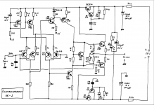
The schematic has a 10 ohm resistor to a virtual ground, so its input impedance is ideally 10 ohm - which is unusually low. Maybe they later changed to a non-inverting configuration, with the signal applied to the bases of the right two 2SB737s and the 10 ohm connected to ground?

The gain from the terminal voltage at the input to the output voltage is ideally -Rfb/R1, where R1 is that 10 ohm, 43 ohm or 100 ohm and Rfb the resistance of that circuit consisting of a 140 ohm resistor, a 300 ohm potmeter and a 2.7 kohm resistor.
The gain from the cartridge's open-circuit voltage (Thevenin voltage, EMF) to the output voltage is lower, ideally -Rfb/(R1 + Zcartridge), where Zcartridge is the impedance of the cartridge. You would get the same gain reduction with cartridge impedance with any amplifier having an input resistance of R1, it's just the voltage division between the amplifier's input resistance and the cartridge impedance.
The gain from the cartridge's open-circuit voltage (Thevenin voltage, EMF) to the output voltage is lower, ideally -Rfb/(R1 + Zcartridge), where Zcartridge is the impedance of the cartridge. You would get the same gain reduction with cartridge impedance with any amplifier having an input resistance of R1, it's just the voltage division between the amplifier's input resistance and the cartridge impedance.
It's also mentioned explicitly in the manual you posted in post #3.
When you type op-amp inverting mode in duckduckgo.com or any other search engine, you will find dozens of websites that explain how this feedback configuration works. In your case the op-amp is not an IC but a discrete amplifier optimized for use as MC headamp, but the principle stays the same.
When you type op-amp inverting mode in duckduckgo.com or any other search engine, you will find dozens of websites that explain how this feedback configuration works. In your case the op-amp is not an IC but a discrete amplifier optimized for use as MC headamp, but the principle stays the same.
It is - and I fully agree; however I had doubts whether this was applied to the MC prepre in particular or the preamplifier itself.
I follow you on the search pattern, but I had focused my searches around the MC-2 unit itself.
Simply because I am not an electronic wizard, but excels more in the acoustical area of music reproduction. Hence, I did not know what to search for. In addition it was only this morning that I stroke luck and found the preamplifier manual while extending my search for information.
I highly appreciate what you have put into light, Marcel, and fully understand the principle of inverted configuration. It all adds up nicely with the theory.
Now - since the sound of the unit in basic configuration is so amazing, I wonder whether it would make sense to build a new power supply instead of that mediocre type that was supplied. As circuit diagram notes voltage is 24 V DC and current is 35 mA on the lousy plug in. I'm pretty sure that there is gains to be had.
What do you all think? Would a shunt regulator following the principles of Borborly or Salas be sufficient?
The simplest way of finding out whether it pays to change your current power supply is to temporarily replace it with six 9Volt alkaline batteries.
With 580mAh they will last long enough to find out whether any acoustical benefit can be noticed.
Alkaline batteries are amongst the cleanest sort of supply available.
If nothing changes, just keep things as they are now.
Hans
With 580mAh they will last long enough to find out whether any acoustical benefit can be noticed.
Alkaline batteries are amongst the cleanest sort of supply available.
If nothing changes, just keep things as they are now.
Hans
The amplifier seems to need only one floating 24 V source, the 10 V Zener (or actually avalanche) diodes then generate +/- 10 V from it. 27 V may already overheat the diodes, so I guess you would need three 9 V batteries in series and a 47 ohm resistor to limit the current. Just three batteries might do if their internal resistance is high enough.
...27 V may already overheat the diodes...
Put a pencil on it. If we trust the numbers, it already has 606mW in the 400mW diodes.
But do we understand how much power-crap reduction is possible here? The R-Z well over 20dB. The cap-multipliers are not pulling their weight at about 40dB. All paths from a rail to the output are via Collectors and typically >>60dB. Maybe 70dB each but three paths so pencil 60dB. Plus 40 plus 20 is 120dB rail rejection relative to output. To input another 20dB-30dB.
There's things I don't like but power cleanup does not look necessary. The designer is not as dumb as we think.
The amplifier seems to need only one floating 24 V source, the 10 V Zener (or actually avalanche) diodes then generate +/- 10 V from it. 27 V may already overheat the diodes, so I guess you would need three 9 V batteries in series and a 47 ohm resistor to limit the current. Just three batteries might do if their internal resistance is high enough.
Right, only one single 24 volt supply is all that’s needed.
In that case two small 1.3Ah 12Volt lead acid batteries could be a perfect choice.
They can be found for ca €7,- each, giving you many hours of time to compare.
Hans
- Status
- This old topic is closed. If you want to reopen this topic, contact a moderator using the "Report Post" button.
- Home
- Source & Line
- Analogue Source
- Help needed understanding this prepreamplifier