Hi SMABB, happy I can contribute ") .
.
Unfortunately, I don't have the manual for this version of the preamp, only this file. I tried to clean up the file a bit for readabillty, and also added the same section from the manual for the first version, which uses replaceble resistors. I also added the same section for the EC-3 MC, which is very similar according to EC support.
.Unfortunately, I don't have the manual for this version of the preamp, only this file. I tried to clean up the file a bit for readabillty, and also added the same section from the manual for the first version, which uses replaceble resistors. I also added the same section for the EC-3 MC, which is very similar according to EC support.
Attachments
Hi SMABB,
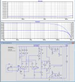
While it seems that you are still struggling a bit with the concept of your amp, I've made a LTSpice model to generate some images, since sometimes one image can tell more than a thousand words.
To start with, I used your info that ca. 35mA current is drawn.
When using a 24V supply, I had to insert an additional 50R in the supply line, so I guess that's also in your supply.
Further did I use a bit more modern transistors, so this will give some slight differences.
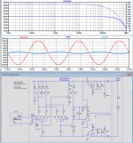
See first image below.
You see three lines in the lower graph, Input- and Output signal plus the signal at the virtual ground input. I have chosen for a gain of 10x or 20dB, resulting in a Rfb=500R versus Rcart=47R.
The virtual ground input is as the name suggest not a real ground, but all current Iin coming from (Cart Voltage) / (Cart Resistance) has to be consumed in Rfb to keep the Virtual Ground input at zero volt level.
This is what is called a Transimpedance Amp where Input current Iin is translated in a Output voltage -Iin*Rfb.
This is only possible when the amp is inverting, so that answers one of your questions.
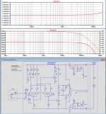
When you insert an internal 47R, Iin now becomes (Cart Voltage) / (Cart Resistance+47R), which is only halve the current as before for this example.
To keep the same gain -Iin*Rfb, Rfb now has to be made twice as large or 1K.
So looking at the second and third image, you still see the same gain of 20dB for both, but the version with the added 47R to the right produces now ca. 3dB more noise and the FR becomes somewhat restricted.
So adding a resistor does not improve sound, unless your cart would become overloaded, which is absolutely never case with these low uA currents.
And there is also none feedback to the cantilever as some worried about in the past, making it harder for the needle to move when connected to a virtual gnd input.
So there are absolutely no negative effects of whatever nature to be expected, just trust your ears.
And about the inverted signal, as long as we don't have the guarantee that the material on the LP has the proper phase, it's just nonsense to switch wires on the Cart, although as an experiment you could try it's a hobby after all.
Hans
P.S. In all conditions, open input and Cart attached, with or without the 100nF at the input, your amp remained stable as a rock with minimal 80 degrees phase margin or even better.
So don't bother about 100pF additional cable capacities either.
.
While it seems that you are still struggling a bit with the concept of your amp, I've made a LTSpice model to generate some images, since sometimes one image can tell more than a thousand words.
To start with, I used your info that ca. 35mA current is drawn.
When using a 24V supply, I had to insert an additional 50R in the supply line, so I guess that's also in your supply.
Further did I use a bit more modern transistors, so this will give some slight differences.
See first image below.
You see three lines in the lower graph, Input- and Output signal plus the signal at the virtual ground input. I have chosen for a gain of 10x or 20dB, resulting in a Rfb=500R versus Rcart=47R.
The virtual ground input is as the name suggest not a real ground, but all current Iin coming from (Cart Voltage) / (Cart Resistance) has to be consumed in Rfb to keep the Virtual Ground input at zero volt level.
This is what is called a Transimpedance Amp where Input current Iin is translated in a Output voltage -Iin*Rfb.
This is only possible when the amp is inverting, so that answers one of your questions.
When you insert an internal 47R, Iin now becomes (Cart Voltage) / (Cart Resistance+47R), which is only halve the current as before for this example.
To keep the same gain -Iin*Rfb, Rfb now has to be made twice as large or 1K.
So looking at the second and third image, you still see the same gain of 20dB for both, but the version with the added 47R to the right produces now ca. 3dB more noise and the FR becomes somewhat restricted.
So adding a resistor does not improve sound, unless your cart would become overloaded, which is absolutely never case with these low uA currents.
And there is also none feedback to the cantilever as some worried about in the past, making it harder for the needle to move when connected to a virtual gnd input.
So there are absolutely no negative effects of whatever nature to be expected, just trust your ears.
And about the inverted signal, as long as we don't have the guarantee that the material on the LP has the proper phase, it's just nonsense to switch wires on the Cart, although as an experiment you could try it's a hobby after all.
Hans
P.S. In all conditions, open input and Cart attached, with or without the 100nF at the input, your amp remained stable as a rock with minimal 80 degrees phase margin or even better.
So don't bother about 100pF additional cable capacities either.
.
Attachments
I noticed that I used 330R instead of 390R as collector resistors in my LTSpice sim because of the difficult to read copy.
The Rfb resistor for a gain of 10 can now be reduced from 500R to 490R.
Apart from this correction, nothing changes in my above comment.
You may wonder why Rfb still has to be 490R instead of 470R for a 47R Cart to get a gain of 10.
This is because the amp does have a limited open loop gain of only 300, so it’s better not to use a closed loop gain higher than 10 to keep enough loop gain.
Hans
Last edited:
Wow Hans - I'm impressed and deeply grateful for all your efforts and knowledge, that you put into this thread. I simply cannot thank you enough
I would never think, that a member would go all the way to build up a digital model and simulate conditions for the sake of explanation.
I sort of had caught the general principles in the design, but now you have nailed it with regards to the series resistor on load. My unit does not have the additional 50 Ohm resistor though
I have run the MC-2 without resistor in load position (R1) for the last 1,5 week, and the unit stays absolutely stable with no signs of buzz or other indications.
Over the last three days I have done a lot of listening tests comparing the sound with the MC-2 in between cartridge (Benz Ruby ll) and preamplifier (Audio Research SP-11 mkll) and the cartridge directly into preamp.
With the MC-2 (R1=0, R2=332) it was quite clear that while the sound was immensely open, spacious and flowing it was also light in bass and treble was emphasized.
With the MC-2 (R1=18, R2=332) bass reemerged some and the excessive treble was tamed compared to Ruby directly into SP-11. Soundstage unaffected and still expansive.
With the MC-2 (R1=47, R2=332) bass was on a par with Ruby directly into SP-11, but treble was now slightly darker. Soundstage unaffected and still expansive.
To me it looks like I should go for R1 slightly lower than the Ruby´s DC of 45 Ohm in order to get the same treble as Ruby directly into SP-11 (which by the way is extraordinarily fantastic and utterly realistic).
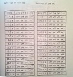
I made repeated tests on all three nights and results were replicated. This indicates to me, that the Norwegians was onto something, when they wrote in the manual for the EC-1: "The correct setting for your system can only be determined by listening, and....". But what were they on to??
Is it the simple loading principle of cartridge into RIAA? But are those loading resistors not in parallel to the signal and not in series with the signal?
I would never think, that a member would go all the way to build up a digital model and simulate conditions for the sake of explanation.
I sort of had caught the general principles in the design, but now you have nailed it with regards to the series resistor on load. My unit does not have the additional 50 Ohm resistor though
I have run the MC-2 without resistor in load position (R1) for the last 1,5 week, and the unit stays absolutely stable with no signs of buzz or other indications.
Over the last three days I have done a lot of listening tests comparing the sound with the MC-2 in between cartridge (Benz Ruby ll) and preamplifier (Audio Research SP-11 mkll) and the cartridge directly into preamp.
With the MC-2 (R1=0, R2=332) it was quite clear that while the sound was immensely open, spacious and flowing it was also light in bass and treble was emphasized.
With the MC-2 (R1=18, R2=332) bass reemerged some and the excessive treble was tamed compared to Ruby directly into SP-11. Soundstage unaffected and still expansive.
With the MC-2 (R1=47, R2=332) bass was on a par with Ruby directly into SP-11, but treble was now slightly darker. Soundstage unaffected and still expansive.
To me it looks like I should go for R1 slightly lower than the Ruby´s DC of 45 Ohm in order to get the same treble as Ruby directly into SP-11 (which by the way is extraordinarily fantastic and utterly realistic).
I made repeated tests on all three nights and results were replicated. This indicates to me, that the Norwegians was onto something, when they wrote in the manual for the EC-1: "The correct setting for your system can only be determined by listening, and....". But what were they on to??
Is it the simple loading principle of cartridge into RIAA? But are those loading resistors not in parallel to the signal and not in series with the signal?
Attachments

SMABB,
Thank for your feedback.
Assuming the AR SP-11 is yours, why do you still need an additional head amp?
The other thing is that when inserting resistors between Cart and MC-2, you change the overall gain unless you also change the 332 feedback resistor.
And changing the gain of an amp with a relatively low loop gain, might have a strong influence on the sound.
With 45R and 332R, gain is 17.1dB
With 45R+18R and 332R, gain is 14.2dB, increase R2 to 464 to keep 17.1dB
With 45R+47R and 332R, gain is 10,9dB, increase R2 t0 678 to keep 17.1dB
So if you want to compare in a accountable way, don't jump to conclusions too fast, this comes very critical.
Another test the opposite way could be, now without R1, change the gain by changing R2. You will also notice a difference in sound
I can only agree with Electrocompaniet that the ultimate proof of the pudding is in the eating, but again, be careful and never change several things at the same time.
Last but not least, the 50R inside your power supply does nor have to be a resistor, it may very well be because internal losses.
As a test, measure the voltage on the voltage input side of the MC-2 while in operation. I guess that it will be ca. 22Volt and if not, you don't have 10Volt zeners inside the MC-2 which is also easy to measure.
Hans
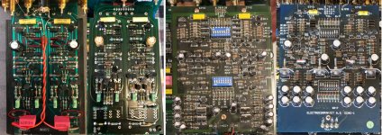
Ok, so I did a picture montage to easier compare the different versions. From left to right is SMABBs EC-MC2, my EC-1 MM/MC from 1987, EC-1 MC from 1989 and EC-3 MC from unknown date, early 90s?
I measured voltage on the EC-1 MC from 1989, since it's easy to spot and measure; 98Vdc over A1-A2. Now, this is clearly a different version and maybe not relevant for the EC-MC2.
But, my EC-1 MM/MC is almost identical to SMABBs EC-MC2, except for power and gain resistors. I could measure it, but not sure where?. The thought was to maybe extract it and use it as standalone headamp, if possible.
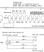
And since my fantasy is much larger than my comprehension, I was wondering if it would be possible to wire it for balanced input/operation, like the EC-3 MC or similar?
I measured voltage on the EC-1 MC from 1989, since it's easy to spot and measure; 98Vdc over A1-A2. Now, this is clearly a different version and maybe not relevant for the EC-MC2.
But, my EC-1 MM/MC is almost identical to SMABBs EC-MC2, except for power and gain resistors. I could measure it, but not sure where?
. The thought was to maybe extract it and use it as standalone headamp, if possible.And since my fantasy is much larger than my comprehension, I was wondering if it would be possible to wire it for balanced input/operation, like the EC-3 MC or similar?
Attachments
Hi Hans, and thanks for all your effort and help. The chronology I believe is as I've described, the naming pattern of EC I can't answer for, sorry. But, the second card on the left EC-1 MM/MC fits the first manual, I believe from 1987. Also you can tell the PCB print in the top right corner is the same - almost (MC-2-3 on mine). The second card from the right is dated on the PCB "06.07.1989". Don't have manual for this version. The card on the far right is from the "fully balanced dual mono" EC-3 with balanced MC input I've posted full pic of earlier. I have the EC-3 MM version, (which is SE), unfortunately not the balanced input MC version...
So if Smabb has the first PCB at the left, he does not have the version with 16 transistors per channel as shown per circuit diagram in the first posting of this thread, true ?
The other thing is, if you want a balanced/differential version, you need two current sense amps per channel instead of one.
Hans
The other thing is, if you want a balanced/differential version, you need two current sense amps per channel instead of one.
Hans
I am (almost) analfabet when it comes to diagrams, I didn't study it. If it's his card in the pic he posted, and it doesn't fit the diagram, I believe you are right.
As for balanced - thanks. I have to study those two cards closely to see if I can spot the difference. I'm a little uncertain of the way Electrocompaniet did it, looking at the schematic in the manual of the EC-3 MC.
As for balanced - thanks
. I have to study those two cards closely to see if I can spot the difference. I'm a little uncertain of the way Electrocompaniet did it, looking at the schematic in the manual of the EC-3 MC.Attachments
Hans,
It seems I am falling a bit behind...
So to catch up from beginning the story goes like this:
My Audio Research SP-11 mkll went into repair with noise on phono input. I borrowed a NOS Musical Fidelity Nu-Vista from my very good friend. The Nu-Vista only has MM, so he also lent me MC-2, as he also had this. That is were it all started; we had no info on the MC-2, and did not know how to match the MC-2 to Benz Ruby, so I went on here for help.
The reason why I would like to continue using the MC-2 is, that in my experience SP-11 needs at least 0,8 mV from a cartridge, otherwise noise will be too evidently and easily recognisable.
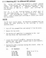
Moving on to the MC-2 I did check as requested. First of all it has to be noticed, that the stock transformer delivers 23,8 V into the MC-2. This is then reduced to 20,8 V on both rails after the 33 Ohm resistor.
The test with varying R1 and keeping R2 constant was just an initial test. I had no idea the sound of the MC-2 would change according to gain setting. I will order a large bunch of different resistors to make a correct test, where gain is kept constant for different values of R1 as you suggest.
I cannot follow your calculation on why you have to choose 490R instead of 470R for keeping gain constant at 10, when R1=47 Ohm. Could you perhaps explain in more detail.
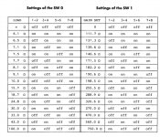
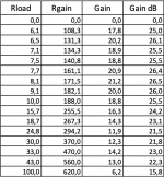
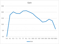
Dagfinn showed us the table for the EC-1 MC from which you could set R1 and R2 using dip switches. Remember it is the actual same circuit board (labeled MC-2-3) as in the MC-2, and the highest values coincide with what was mentioned in the original manual for the MC-2. I have made a table and graphics based on these values for reference. What information do you get from this?
Steen
It seems I am falling a bit behind...
So to catch up from beginning the story goes like this:
My Audio Research SP-11 mkll went into repair with noise on phono input. I borrowed a NOS Musical Fidelity Nu-Vista from my very good friend. The Nu-Vista only has MM, so he also lent me MC-2, as he also had this. That is were it all started; we had no info on the MC-2, and did not know how to match the MC-2 to Benz Ruby, so I went on here for help.
The reason why I would like to continue using the MC-2 is, that in my experience SP-11 needs at least 0,8 mV from a cartridge, otherwise noise will be too evidently and easily recognisable.
Moving on to the MC-2 I did check as requested. First of all it has to be noticed, that the stock transformer delivers 23,8 V into the MC-2. This is then reduced to 20,8 V on both rails after the 33 Ohm resistor.
The test with varying R1 and keeping R2 constant was just an initial test. I had no idea the sound of the MC-2 would change according to gain setting. I will order a large bunch of different resistors to make a correct test, where gain is kept constant for different values of R1 as you suggest.
I cannot follow your calculation on why you have to choose 490R instead of 470R for keeping gain constant at 10, when R1=47 Ohm. Could you perhaps explain in more detail.
Dagfinn showed us the table for the EC-1 MC from which you could set R1 and R2 using dip switches. Remember it is the actual same circuit board (labeled MC-2-3) as in the MC-2, and the highest values coincide with what was mentioned in the original manual for the MC-2. I have made a table and graphics based on these values for reference. What information do you get from this?
Steen
Attachments
Smabb,
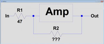
Look at the image below with R1 =47.
What value should R2 have to get a gain of 10 ?
Well, the answer depends on the gain of the amp.
Let's say we have 1mV at the input and because of the wanted gain of 10, we want -10mV at the output.
1)Now suppose the amp has a gain of 5.
That means that to get -10mV at the output, we would need 10mV/5=2mV at the junction of R1 and R2.
But because there is only 1mV at the input, this will never happen because no matter how large R2, output cannot exceed -5V with 1mV at its input.
2)Now suppose Gain is 270
To get -10mV at the output, we need 10mV/270=37.7uV at the junction of R1 and R2.
Current through R1 is now (1mV-37.7uV)/47R=20.5uA.
R2 now has to be (10mV+33.7uV)/20.5uA = 490R.
It's obvious that you have the second situation, hope you can follow my calculation.
Hans
Attachments
Thanks again, Hans
Referring to your simple model it is quite clear to me now, how you calculate the 490R. Very nice of you taking the time to explain. Much appreciated as always
What do you (and other members) think of Electrocompaniet´s settings referred to in my previous post?
They are using a high gain of approx. 20 for cartridges loaded with resistance lower than or equal 10 Ohm, and a gain of approx. 13 for cartridges with load resistor higher than 20. Is there a natural explanation for these settings (assuming there is, I just don't now why myself...)?
P.s. The vision regarding a maximum gain of 10 with your MC2 was the reason to advise you to try a number of different gain settings with R2 whith the Cart directly connected without R1.
So learn to trust your ears and don’t rely too much on opinions from other people including myself.
Hans
So learn to trust your ears and don’t rely too much on opinions from other people including myself.
Hans
Hans,
Don't worry - for the past 35 years I have used my ears quite extensive. I know how live acoustical as well as amplified music sounds to my ears. Those are my references.
Starting from scratch I had interest in understanding this MC-2, as it does something that makes music flow in the room in front of me. Manuals were scarce with info, so I turned to this knowledgable forum for help.
Thanks to you and other contributors I was not disappointed. I have gained tremendous knowledge about the little black box.
I will revert with comments beginning of next year, when resistors have arrived and the MC-2 has been tested with different loadings but constant gain.
.... using a high gain of approx. 20 for cartridges loaded with resistance lower than or equal 10 Ohm, and a gain of approx. 13 for cartridges with load resistor higher than 20. Is there a natural explanation for these settings.....
Coil space/mass is limited. Few turns of fat wire makes a low voltage and impedance. More turns of skinny wire makes a higher voltage and impedance.
It is not universal or exact. Twice the turns is twice voltage but (in same space) four times the impedance. But the Designer can refine magnet strength, clearance, leverage for other results.
The question concerned overall gain and why it should be higher with a lower combination of Rcart and Rload instead of using a constant gain independant of the used Cart since Rf can be selected accordingly.
The answer lies probably in the differing FR with low source resistance in combination with the 100nF input cap.
With a gain of 10 and a 10R source resistance, you will get a 4dB peak at ca. 2Mhz.
Increasing gain to 20, reduces this peak to 1.5dB.
With a higher source impedance like Smabb has, this peak is completely gone and gain can be lowered.
Hans
- Status
- This old topic is closed. If you want to reopen this topic, contact a moderator using the "Report Post" button.
- Home
- Source & Line
- Analogue Source
- Help needed understanding this prepreamplifier