Allright then....
Just a quick note:
An Australian guy got hold of one. Here's what he wrote:
"First thing I did was substitute a more solid power supply. I liked that.
Then I upped the gain massively.
Then I changed the impedance match also.
These two changes were not resistor values you'd expect but it's sounding really good now. It's got good PRAT. It's quick and very musical. I think my transformer had better more solid tone and even better dynamics but this device is very clean, low distortion, very open and very musical. Musical is it's best attribute I think in my system."
He does explicitly mention benefits from a larger transformer, but focuses most on benefits from load matching and upping the gain. That comes as no surprise..
1st question: Yes, as stated above.Is the circuit inverting the input signal?
Meaning I will have to alter the wiring connector pins on the cartridge?
2nd question: Not necessarily. I doubt that the human hearing sense can discern between natural and inverted phase. On top of that, one ground pin might be tied to the catridge's case, so inverting the phase of this channel inevitably will introduce hum.
Best regards!
This circuit is... well, I wouldn't say a waste of some perfectly good 2SB737s, but not exactly very good use of them either.
Where your average MC prepre tends to focus on low noise with linearity being less of a priority (levels are, after all, quite small), this one is quite the opposite, with the usual bad tradeoff between input impedance and input noise of an inverting circuit. I am not convinced that this set of tradeoffs has any practical benefits, quite the contrary, it makes the circuit quite complex while giving good performance where it doesn't matter all that much but mediocre performance where it does.
Possible the circuitry had been adapted from a full phonopre or something. In any case, this smells of design by agenda.
Thanks for chiming in....
I assume you are referring to basics, that resistors are exceptional sources of noise. Bigger resistors make more noise than little resistors.
Would you mind clarify further the trade offs as seen from your POV?
Electrical circuits are not among my strongest offerings coming from a base in the acoustical area.
What I can tell you by ear is, that the MC-2 is exceptionally low on noise and the sound (or music ) is exceptionally beautiful.
I assume you are referring to basics, that resistors are exceptional sources of noise. Bigger resistors make more noise than little resistors.
Would you mind clarify further the trade offs as seen from your POV?
Electrical circuits are not among my strongest offerings coming from a base in the acoustical area.
What I can tell you by ear is, that the MC-2 is exceptionally low on noise and the sound (or music
) is exceptionally beautiful.R1 sets the input impedance, so you can't make it arbitrarily small, so you can't make its noise voltage density arbitrarily small, and meanwhile it is connected straight in series with the input. That's the main disadvantage of this topology (another one is the inversion).
I’m sorry, but I don’t share your opininion at all and I fully reject your comment on using an inverting topology.This circuit is... well, I wouldn't say a waste of some perfectly good 2SB737s, but not exactly very good use of them either.
Where your average MC prepre tends to focus on low noise with linearity being less of a priority (levels are, after all, quite small), this one is quite the opposite, with the usual bad tradeoff between input impedance and input noise of an inverting circuit. I am not convinced that this set of tradeoffs has any practical benefits, quite the contrary, it makes the circuit quite complex while giving good performance where it doesn't matter all that much but mediocre performance where it does.
Possible the circuitry had been adapted from a full phonopre or something. In any case, this smells of design by agenda.
It may be that blind tests have shown that we can theoretically hear a difference but a difference does not automatically mean a worsened sound.
About noise production: a non inverting pre will always need a low value resistor in it’s feedback loop, where in this topology you can discard the input resistor completely by just using the Cart’s source resistance, so it’s even superior noise wise.
My personal experience so far with virtual gnd pre-pre’s is very positive, in line with several test in Stereophile.
It has become my favourite topology.
Hans
R1 sets the input impedance, so you can't make it arbitrarily small
Quite a few more recent designs set it at zero and work as pure I/V stages. Some of them are subjectively very successful, although i would expect mostly with low dcr carts.
The phonocard clones discussed here years ago is one such example and to my knowledge the first commercial design of this type.
An audible difference that shouldn't be there at least means a less realistic sound.
Dunno what that means. Switching the headshell wiring from one type to another leads often to extreme audible differences. Yes, it shouldn't be there, but is the sound less realistic because of that?
So - here is some more food for thoughts...
First of all thank you so much for all the inspiring and knowledgeable comments from all of you. They are highly appreciated. I definitely feel we are getting somewhere.
A very good friend of mine helped me optimise the MC-2 with correct resistor values for a Benz Micro Ruby (which also happens to be his), that I have on loan.
We used Holco and Shinkoh resistors. The change in sound was noticeable from the original R1=18 Ohm and R2=332 Ohm. Now the Benz is loaded with 47 Ohm and gain set accordingly.
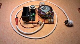
Now - my very good friend also build me a shunt regulator based on a Salas design. Only in a test bed with what parts were available, hence the trafo is rather big and so is the cooling fin (see attached picture). We have a steady 23,8 V on the inside of the MC-2, just as with the original trafo.
But the sound.... differs... a lot
- Soundstage became really wide and deep with so many layers.
- Midbass was tightened up and the low bass to mid bass is now very detailed
- Dynamics improved considerable and soundstage is rock solid.
- Treble sounds truer, more real and much, much more detailed.
So a generous power supply unit is definitely a way to go even for this modest amount of current drawn from the circuit. A shunt regulator may not be the best alternative, but what do you members suggest? A regular PSU with filtering, shunt regulator or...??
First of all thank you so much for all the inspiring and knowledgeable comments from all of you. They are highly appreciated. I definitely feel we are getting somewhere.
A very good friend of mine helped me optimise the MC-2 with correct resistor values for a Benz Micro Ruby (which also happens to be his
), that I have on loan.We used Holco and Shinkoh resistors. The change in sound was noticeable from the original R1=18 Ohm and R2=332 Ohm. Now the Benz is loaded with 47 Ohm and gain set accordingly.
Now - my very good friend also build me a shunt regulator based on a Salas design. Only in a test bed with what parts were available, hence the trafo is rather big and so is the cooling fin (see attached picture). We have a steady 23,8 V on the inside of the MC-2, just as with the original trafo.
But the sound.... differs... a lot
- Soundstage became really wide and deep with so many layers.
- Midbass was tightened up and the low bass to mid bass is now very detailed
- Dynamics improved considerable and soundstage is rock solid.
- Treble sounds truer, more real and much, much more detailed.
So a generous power supply unit is definitely a way to go even for this modest amount of current drawn from the circuit. A shunt regulator may not be the best alternative, but what do you members suggest? A regular PSU with filtering, shunt regulator or...??
Attachments
Hi SMABB,
I can only repeat, two 12 Volt lead acid batteries gives you the best possible reference to compare mains connected power supplies, you may be surprised.
A Jung Didden supply may be one of the best supplies that I can advise you.
See a large test of many supplies in Linear Audio Vol 4.
The other comment is that you have inserted a 47R resistor in line with your Cart.
This resistor is producing nothing but additional 1nV/rtHz noise, which should be avoided.
You can connect your cart directly to your amp without this 47R resistor, resulting in 6dB more output and 3dB less S/N.
Don't be afraid, this is exactly how I have connected my Benz LP, nothing can go wrong.
You could take a step in between and use 10R instead of 47R if you still feel a bit unsecure.
But believe me, this gives the best possible soundstage with the lowest S/N.
Hans
Last edited:
Leaving out the resistor means the cable capacitance is connected straight to the input, which may or may not cause instability. Besides, it increases the L/R time constant and causes some loss of treble, but it could very well be that that only happens well in the ultrasonic region (no idea what inductance and resistance the MC cartridge has).
Regarding noise, assuming that a typical MM cartridge has an inductance of about 500 mH and that an MC cartridge has 10 times less output voltage, a 30 ohm series resistor at the input has about the same impact on the total RIAA- and A-weighted signal to noise ratio as the 47 kohm shunt resistor in a MM amplifier. That is, it can be audible in between records. 47 ohm is almost 2 dB worse than 30 ohm.
Regarding noise, assuming that a typical MM cartridge has an inductance of about 500 mH and that an MC cartridge has 10 times less output voltage, a 30 ohm series resistor at the input has about the same impact on the total RIAA- and A-weighted signal to noise ratio as the 47 kohm shunt resistor in a MM amplifier. That is, it can be audible in between records. 47 ohm is almost 2 dB worse than 30 ohm.
Hi Marcel,
1) Fortunately your suspect is not valid in the real world of MC carts.
Take my Cart, Rcart=38R and Lcart=15uH.
This gives a -3dB point at 403Khz, not exactly a thing to worry about.
So assuming a 50 mH coil because output is 10 times lower is more then a factor 1000 to pessimistic.
2) The other thing you mention is cable capacity, which does not play any role with these values,
but also keep in mind that in case of using a virtual input, this cable capacity is directly in parallel to this almost zero ohm virtual input impedance, thereby having even less effect as when the Cart is loaded with 47R inside the preamp.
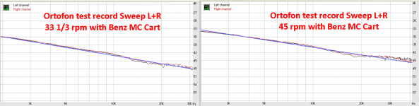
3) To prove the above, have a look at the following graphs made from an Ortofon test record, cut with constant velocity and played with a straight non Riaa preamp.
Graph was made with my cart directly connected to the virtual input of the preamp and should ideally result in a -10dB/oct downwards slope.
As you can see, the result is almost exemplary up to 40Khz.
To conclude, don't keep hanging in figures, you always have to try and test with your ears.
Hans
P.s. also keep in mind the ever growing number of commercially available MC pre amps with virtual inputs.
Never any problem was reported with instability issues.
1) Fortunately your suspect is not valid in the real world of MC carts.
Take my Cart, Rcart=38R and Lcart=15uH.
This gives a -3dB point at 403Khz, not exactly a thing to worry about.
So assuming a 50 mH coil because output is 10 times lower is more then a factor 1000 to pessimistic.
2) The other thing you mention is cable capacity, which does not play any role with these values,
but also keep in mind that in case of using a virtual input, this cable capacity is directly in parallel to this almost zero ohm virtual input impedance, thereby having even less effect as when the Cart is loaded with 47R inside the preamp.
3) To prove the above, have a look at the following graphs made from an Ortofon test record, cut with constant velocity and played with a straight non Riaa preamp.
Graph was made with my cart directly connected to the virtual input of the preamp and should ideally result in a -10dB/oct downwards slope.
As you can see, the result is almost exemplary up to 40Khz.
To conclude, don't keep hanging in figures, you always have to try and test with your ears.
Hans
P.s. also keep in mind the ever growing number of commercially available MC pre amps with virtual inputs.
Never any problem was reported with instability issues.
Attachments
Last edited:
1) I don't estimate it as 50 mH, I just wrote I had no idea. Good to know that this isn't an issue.
2) I wrote about the possible impact of cable capacitance on loop stability, which is related to what happens around the point where the magnitude of the loop gain drops to unity. You can't assume virtual ground behaviour when analysing loop stability, because there is not much of a virtual ground left when the magnitude of the loop gain has dropped to about 1.
2) I wrote about the possible impact of cable capacitance on loop stability, which is related to what happens around the point where the magnitude of the loop gain drops to unity. You can't assume virtual ground behaviour when analysing loop stability, because there is not much of a virtual ground left when the magnitude of the loop gain has dropped to about 1.
Conditions for stability to be met at a loop gain of 1 are valid for all amplifiers inverting and non inverting, so this is not something special for an inverting MC amp using the Carts resistance as Rs connected to a virtual input.
Everything is completely covered by general feedback rules.
Hans
Everything is completely covered by general feedback rules.
Hans
Of course, and those general feedback rules show that adding extra negative phase shift in the loop could make it unstable, like when you connect the cable capacitance straight to the inverting input. With an extra resistor between the cable and the amplifier, at least that resistor causes a zero in the left half plane / decouples the capacitance from the feedback loop at high frequencies.
It will only be an issue when the loop bandwidth is large or the cable is long, though. For example, with 47 ohm and a 100 pF cable (1-metre low-capacitance cable), you theoretically get a zero at -212.8 Mrad/s corresponding to a corner frequency of 33.86 MHz. In fact it will be somewhat worse because you get close to the first transmission line resonance (assuming polyethylene insulation, the cable is a quarter wavelength long at 50 MHz).
With 47 ohm and a 1-metre cheap PVC cable of 280 pF, it's -75.99 Mrad/s and 12.09 MHz, first transmission line resonance around 37 MHz.
With 47 ohm and a 10-metre cheap PVC cable of 2.8 nF, it's -7.599 Mrad/s and 1.209 MHz, and you get transmission line resonances from 3.7 MHz onward.
- Status
- This old topic is closed. If you want to reopen this topic, contact a moderator using the "Report Post" button.
- Home
- Source & Line
- Analogue Source
- Help needed understanding this prepreamplifier