Hi guys,
some time ago i bought this Onkyo TA-2600 3-head cassette deck.
I'm in the process of adjusting it according to the service manual.
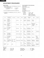
Attached is the page with the adjustments (please right-click > open in an new tab for full image view).
The adjustments consist of 8 steps to be executed with that order (1 to 8).
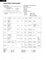
I have successfully completed steps 1 to 4. I'm stuck with some terminology and questions about steps 5 to 8...
Step 5. Bias Trap
In the "Test Tape" column it says METAL TAPE, i guess it means to use a blank metal tape for this test. However in the "Line Input" column there is no input suggested at all.
So, how should this step be completed? Just put a blank metal tape in there and hit the RECORD button then proceed with the adjustment?
If so, where the Input Level control knob of the deck should be set to?
Step 6. HX-PRO
In "Remarks" column it states: "R-467 R-468 counter clock wise" (those are potentiometers on the circuit board)
I don't get it, should those potentiometers turned all the way to the left (counterclockwise) before the adjustment begins?
Step 7. Bias current
In the last column of this test, called "Remarks" it mentions "Input VR Maximum" . What does that mean? Is it related to the Input Level control knob?
Step 8. Record level
Here i guess i need to feed the RCA inputs of the deck with 1KHz sine wave signal and begin with the adjustment.
But in column "Test tape" it does not mention anything. Shouldn't I record the signal to a tape in order to compare Record and PB levels?
Also, again in column "Remarks" , it says "Input VR maximum" which i don't know where it is referring to...
Any help ?
some time ago i bought this Onkyo TA-2600 3-head cassette deck.
I'm in the process of adjusting it according to the service manual.
Attached is the page with the adjustments (please right-click > open in an new tab for full image view).
The adjustments consist of 8 steps to be executed with that order (1 to 8).
I have successfully completed steps 1 to 4. I'm stuck with some terminology and questions about steps 5 to 8...
Step 5. Bias Trap
In the "Test Tape" column it says METAL TAPE, i guess it means to use a blank metal tape for this test. However in the "Line Input" column there is no input suggested at all.
So, how should this step be completed? Just put a blank metal tape in there and hit the RECORD button then proceed with the adjustment?
If so, where the Input Level control knob of the deck should be set to?
Step 6. HX-PRO
In "Remarks" column it states: "R-467 R-468 counter clock wise" (those are potentiometers on the circuit board)
I don't get it, should those potentiometers turned all the way to the left (counterclockwise) before the adjustment begins?
Step 7. Bias current
In the last column of this test, called "Remarks" it mentions "Input VR Maximum" . What does that mean? Is it related to the Input Level control knob?
Step 8. Record level
Here i guess i need to feed the RCA inputs of the deck with 1KHz sine wave signal and begin with the adjustment.
But in column "Test tape" it does not mention anything. Shouldn't I record the signal to a tape in order to compare Record and PB levels?
Also, again in column "Remarks" , it says "Input VR maximum" which i don't know where it is referring to...
Any help ?
Attachments
If you're just setting up the deck to record, why don't you find an owners manual. Unless you're a technician, a service manual isn't going to be of much value.
I see the Onkyo TA-2600 Stereo Cassette Tape Deck Manual | HiFi Engine has one listed.
jeff
I see the Onkyo TA-2600 Stereo Cassette Tape Deck Manual | HiFi Engine has one listed.
jeff
When it comes to bias setting, with 3 head deck, i set bias during the test recording, and switching between the incoming signal and recorded signal, on the fly. Ideally using good headphones. With good tape, you can find the spot when incoming and just recorded is identical. The recording level depends on the tape type. Does not have to be metal, it should be done for each tape.
Ps: have not seen your reply...my post is irrelevant now
Ps: have not seen your reply...my post is irrelevant now
Last edited:
I'm trying to calibrate the deck, not to record a cassette
Even the PB/REC head was out of adjustment...if you get what i mean...
10-4. Sorry can't help.

Looks like a nice deck.
jeff
10-4. Sorry can't help.
Looks like a nice deck.
jeff
no worries, it's not an routine task for most of us anyways...
Bias trap is simply an adjustment to remove the high frequency bias residue. You have NO signal applied and with the bias set to its highest value (so that will be for Metal tapes) simply use a scope on the test points (a DVM probably won't cut it here) and tweak to get the best null on the bias residual.
(You can use any tape by the way or even have no tape present if you defeat the interlocks for this)
Record level setting etc doesn't matter for this adjustment, just make sure no signal is applied.
(You can use any tape by the way or even have no tape present if you defeat the interlocks for this)
Record level setting etc doesn't matter for this adjustment, just make sure no signal is applied.
thanks guys. I will re-visit the bias trap again tonight.
I'm done with all the other adjustments and i'm pretty satisfied with the outcome.
Speed was spot on, good sign for the motor...
PB/REC head azimuth was completely out of alignment.
Playback level was out too but not much.
Meter needed small adjustments.
HX-Pro almost OK.
Bias current out of adjustment.
Looks like either someone messed around with the PB/REC potentiometers in the past because record level was way out (something that I noticed while trying to record my first tape), OR some electronic parts are really deteriorating in there...
Well, maybe i need to re-visit the record levels adjustment again because i get slightly lower level for PB than for the REC. Just want to make sure I did the best adjustment there, deck is ~30 years old so i don't expect everything perfect.
@Mooly,
Yeap, I'm using a PC USB scope for this. During my first try to adjust the BIAS Trap, I wasn't able to detect any changes while I was turning the bias trap inductors. Maybe i did something wrong...
I have issues with adjusting the Bias trap (please note I'm talking about the Bias Trap adjustment, NOT the Bias Current adjustment).
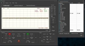
It looks like turning the coils either direction does not make much of a difference to the AC RMS voltage readings i get on the oscilloscope (I use a USB oscilloscope with software and display output on my laptop).
It stays around the 20mV AC RMS area.
The amplitude does not change as well...
The measured frequencies of the Bias Trap are in the >100KHz area.
Sometimes when I stop the Record mode of the deck, the readings on my scope remain like if I was on record mode, some other times when i stop the Record mode on the deck, the scope readings change as well and fall to about 2 mV - 1.8 mV.
Also the amplitude is barely visible on the scope as you can see in the screenshot, I cannot get anything cleaner than that.
not sure if I'm setting the scope correctly or if the scope gets the correct readings or if there is something wrong with the bias trap coils or any other component.
Any advise?
Attachments
ok so there is some weird behavior of the bias trap measurements...
I powered off the deck and left it powered off for 2 hours or so.
Then I powered on and hit again the "Run" button on my scope to get new measurements.
This time it was showing both channels AC RMS at around 25mV and frequency at around 35KHz...
Then I noticed that the AC voltage began to drop and the frequency began to rise on my scope.
After 10 minutes of continuous measurement, I watched the voltage dropping to around 18.5 mV and the frequency rise to around 145KHz for both channels.
After 20 minutes of continuous measurement the voltage dropped a bit more and seems to stabilize at ~17 mV . But the frequency does not register anymore on my scope.
Is that normal? Am I doing something wrong?
As a generalisation the bias voltage after the trap should swing from a minimum up to several volts either side of the null point.
Millivolt figures suggest something isn't right with the measurement (assuming the deck is working OK which I think it is).
Would need to see the circuit of that area but try measuring the bias oscillator itself before the traps. There should normally be tens of volts of bias signal.
Always use a divider probe for these measurements.
I'm just looking at spec of your scope... input impedance 100k and 20pF.
That's really low. A scope with a divider probe is 10meg and around 10pF. The probe itself would have a bandwidth of many many MHz.
So hard to say... your scope input may be damping the wanted signal to much.
That's really low. A scope with a divider probe is 10meg and around 10pF. The probe itself would have a bandwidth of many many MHz.
So hard to say... your scope input may be damping the wanted signal to much.
Hi Mooly, all,
although I suspect the scope is not up to the task...
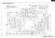
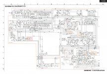
I attach here the schematics and diagrams if you'd have some time to take a look at it...
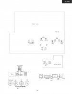
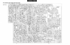
While Viewing the "3-PC Board Bottom Side.jpg" image, (please right-click > open in a new tab for the full size image),
the coils I'm trying to adjust are the L101 and L102 a bit below the inverted "ONKYO" writing, and the scope probes attach to TP1 and TP2 which are exactly below the J135 Dolby Processor IC.
although I suspect the scope is not up to the task...
I attach here the schematics and diagrams if you'd have some time to take a look at it...
While Viewing the "3-PC Board Bottom Side.jpg" image, (please right-click > open in a new tab for the full size image),
the coils I'm trying to adjust are the L101 and L102 a bit below the inverted "ONKYO" writing, and the scope probes attach to TP1 and TP2 which are exactly below the J135 Dolby Processor IC.
Attachments
-
 7-Adjustment Procedure 2 of 2.jpg196.3 KB · Views: 54
 -
 6-Adjustment Procedure 1 of 2.jpg408.5 KB · Views: 52
 -
 5-Schematic 2 of 2.jpg994.6 KB · Views: 53
 -
 4-Schematic 1 of 2.jpg1,001.2 KB · Views: 83
 -
 3-PC Board Bottom Side.jpg1 MB · Views: 92
 -
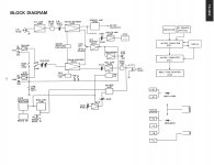
 2-Block Diagram.jpg331.4 KB · Views: 86
 -
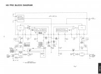
 1-HX Pro Block Diagram.jpg315.9 KB · Views: 87
Seeing that makes a bit more sense
The bias traps I was thinking of in general would have been on the record amp output... so this is totally different... and these tune out the leakage of bias that the play head is picking up while in record mode.
So your scope should be OK here as it is a much lower impedance point than I was referring to earlier.
Have you tried looking at the signal on the top of C113 that goes to the coil itself. See if you can pick the bias leakage up there and whether it nulls out.
Also I would say now (different to what I said at the start) that you should have a tape in the slot so as to replicate normal use. Metal tape will set the bias to max which makes the adjustment easier.
If you still can't see much then look at the other side of the coil (R105) to see if there is much more bias signal there.
Hi Mooly, all,
So I did a bunch of measurements all over again, multiple times.
I have also replaced my PC scope with another (Velleman PCSU200) which has better characteristics (and closer to a regular scope) and bought new probes for it (AST Labs 100MHz with x10 option) in an effort to eliminate the scope as a point of failure...
I took measurements at TP1 (L Ch.) and TP2 (R Ch.) which according to the manual are the test points for adjusting the Bias Trap
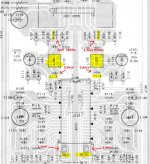
I also took measurements at C113 and R105 (L Ch.) and C114 and R016 (R Ch.)
Those are the capacitors and resistors on either side of the coils L101 and L102 (for L and R channel respectively)
I attach a picture where I marked the places I took my measurements at and the values.
So, switching on and off the REC of the deck (using metal tape) it looks like i get almost no voltage at the test points, and I get almost no voltage at the capacitors. The slight voltage that my probes read there does not change with REC going or REC off.
Scope does not register any frequency either.
The only place i get a change in voltage when switching to recording mode (REC on) is the resistors R105 and R106.
There is get these:
With REC on (Metal cassette in)
R105 -> 4mV AC RMS and 96KHz freq.
R106 -> 3.5mV AC RMS and 95KHz freq.
With REC off (stopped recording)
R105 -> same as test points TP1 which is around 1mV AC RMS
R106 -> same as test points TP2 which is around 1mV AC RMS
I am really lost. Am I measuring correctly? OR is it some component failure somewhere on the board?
I believe I'm measuring correctly because i had no problems to take measurements and adjust the Bias Current which is Adjustments step 7 in the manual and has to do with similar coils and similar test points too...
Any ideas what to look next?
EDIT: I tried to use x10 mode for the probes/scope, it does not look like this type of measurement needs x10 mode...
So I did a bunch of measurements all over again, multiple times.
I have also replaced my PC scope with another (Velleman PCSU200) which has better characteristics (and closer to a regular scope) and bought new probes for it (AST Labs 100MHz with x10 option) in an effort to eliminate the scope as a point of failure...
I took measurements at TP1 (L Ch.) and TP2 (R Ch.) which according to the manual are the test points for adjusting the Bias Trap
I also took measurements at C113 and R105 (L Ch.) and C114 and R016 (R Ch.)
Those are the capacitors and resistors on either side of the coils L101 and L102 (for L and R channel respectively)
I attach a picture where I marked the places I took my measurements at and the values.
So, switching on and off the REC of the deck (using metal tape) it looks like i get almost no voltage at the test points, and I get almost no voltage at the capacitors. The slight voltage that my probes read there does not change with REC going or REC off.
Scope does not register any frequency either.
The only place i get a change in voltage when switching to recording mode (REC on) is the resistors R105 and R106.
There is get these:
With REC on (Metal cassette in)
R105 -> 4mV AC RMS and 96KHz freq.
R106 -> 3.5mV AC RMS and 95KHz freq.
With REC off (stopped recording)
R105 -> same as test points TP1 which is around 1mV AC RMS
R106 -> same as test points TP2 which is around 1mV AC RMS
I am really lost. Am I measuring correctly? OR is it some component failure somewhere on the board?
I believe I'm measuring correctly because i had no problems to take measurements and adjust the Bias Current which is Adjustments step 7 in the manual and has to do with similar coils and similar test points too...
Any ideas what to look next?
EDIT: I tried to use x10 mode for the probes/scope, it does not look like this type of measurement needs x10 mode...
Attachments
-
 6-Adjustment Procedure 1 of 2.jpg408.5 KB · Views: 50
 -
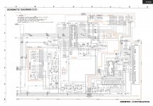 5-Schematic 2 of 2.jpg924.1 KB · Views: 55
 -
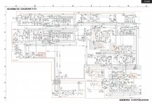 4-Schematic 1 of 2.jpg931.6 KB · Views: 39
 -
 3-PC Board Bottom Side.jpg968.1 KB · Views: 38
 -
 2-Block Diagram.jpg331.4 KB · Views: 51
 -
 1-HX Pro Block Diagram.jpg315.9 KB · Views: 106
 -
 Capture2.JPG208.7 KB · Views: 44
 -
 7-Adjustment Procedure 2 of 2.jpg196.3 KB · Views: 40
Last edited:
You must be measuring correctly if you are on R105/106. Is the 4mv etc a true reading or is it what the scope shows plus using a divider probe (so actually 40 millivolts).
Sometimes service manuals and circuit designs do have adjustments that just don't seem to do much, it happens...
Can you see any of this high frequency signal on the output of the tape head amp itself which is on C105 and C107?
If the deck is all working correctly (recording well) then there isn't really any problem. Not having any HF signal is just a bonus because none is leaking through.
If you want to do more tests then use the divider probe and look at the bias oscillator output itself by measuring across the erase head in record with a metal tape. There should be several tens of volts of high frequency signal at a frequency specified in the manual (was it 105kHz from memory).
- Status
- This old topic is closed. If you want to reopen this topic, contact a moderator using the "Report Post" button.
- Home
- Source & Line
- Analogue Source
- Help understand a few cassette deck adjustments/calibration steps