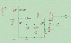
It's too quiet in here, therefore I present this conceptual diagram of a phonostage I am working on. Mind that is it not complete and that R and C values can differ slightly from what is optimal.
A rough prototype with DC servo, LM317/337 regs for the opamps and zener-follower for the front-end succeeds in sounding remarkably dynamic and very transparent in the lower registers, this with a 0.4mV cartridge.
Noise is almost absent, and measured distortion is -70dB, H2 mostly, with only a tiny little bit of H3 coming in above 2kHz.
Attachments
Werner said:It's too quiet in here, therefore I present this conceptual diagram of a phonostage I am working on. Mind that is it not complete and that R and C values can differ slightly from what is optimal.
A rough prototype with DC servo, LM317/337 regs for the opamps and zener-follower for the front-end succeeds in sounding remarkably dynamic and very transparent in the lower registers, this with a 0.4mV cartridge.
Noise is almost absent, and measured distortion is -70dB, H2 mostly, with only a tiny little bit of H3 coming in above 2kHz.
Hi Werner,
That's pretty crude compared to this one:
http://www.diyaudio.com/forums/showthread.php?s=&threadid=1794&highlight=
Elso, if I wanted to design a discrete folded-cascode opamp I would have done just that, don't worry. But the overall aim was simplicity.
And in case you wonder why the cascode current is set with just a resistor, I can tell you that I was following a quite illustrious example there (and I hope no-one will take revenge on me for that).
And in case you wonder why the cascode current is set with just a resistor, I can tell you that I was following a quite illustrious example there (and I hope no-one will take revenge on me for that).
Werner said:Elso, if I wanted to design a discrete folded-cascode opamp I would have done just that, don't worry. But the overall aim was simplicity.
And in case you wonder why the cascode current is set with just a resistor, I can tell you that I was following a quite illustrious example there (and I hope no-one will take revenge on me for that).
Hi Werner,
Your frontend is discrete.

Noise?
Hi Upopa Epops,
FETs give better sound quality. John Curl was able to achieve fenomenal signal to noise ratios in the Vendetta MC-phono amp with FETs.
I do not complain about noise either with off the shelve 2SK389BL's
Upupa Epops said:For optimal noise parametres by MC is better to use BJT devices - fets are optimal for MM.
Hi Upopa Epops,
FETs give better sound quality. John Curl was able to achieve fenomenal signal to noise ratios in the Vendetta MC-phono amp with FETs.
I do not complain about noise either with off the shelve 2SK389BL's
"better to use BJT devices"
Wouldn't it be wonderful if people just read what is written? When I say that noise is almost absent, then I mean that noise is almost absent.
And I mean so even compared to the sub-1nV/sqrt(Hz) BJT-stages I have lying around.
Anyway, try to build the same/similar design with BJTs. Hawksford did, and could not do without a number of elcaps in the front-end signal path.
Elso, from you last reply I gather that you found the hidden reference in the third posting from the top?
"Could it be adapted for MM gain also ?"
Sort of. You could try with a lower gain from the opamp, running the front-end still at 30dB or so. This works, but drives the input FET at much higher input and output levels, and distortion may rise.
You could lower the FET's gain to 10 or even less, simply by scaling down R1. But in that case you'd have to scale up C1 to maintain proper RIAA equalization.
Fine if you can get decent 330nF caps, precision-matched and of known value.
Even so I'd still expect more distortion.
As an aside, given the non-linearities that moving coils exhibit in their frequency response I am slowly being driven to conclude that trying to get a phono preamp to within .1 dB of the RIAA standard is utterly useless, and may actually be counter-productive.
Thanks Werner,
My cartridge is a 3mV VDH MC-Two, and with a similar first stage topology ( Thorstenized Pacific.... sk117) sounded ok to me.
Could I use the 117s (BL 5ma IDSS..) I have on hand instead of 369 ?
For a total gain around 40db could you please advice me component values for the 627 ?
My cartridge is a 3mV VDH MC-Two, and with a similar first stage topology ( Thorstenized Pacific.... sk117) sounded ok to me.
Could I use the 117s (BL 5ma IDSS..) I have on hand instead of 369 ?
For a total gain around 40db could you please advice me component values for the 627 ?
I wouldn't call a cascoded Pacific 'similar' to the above circuit. As seen from the point of view of the power supply they are quite massively different. And the same holds for the voltage seen by the input FETs drain.
I only use 2sk170 and 2sk369. These are the only JFETs I have, no experience with the 117.
I can't give values for 40dB, as the whole network around the opamp must be carefully simulated for the intended frequency response, preferrably with the actual measured component values of the Cs in place.
I only use 2sk170 and 2sk369. These are the only JFETs I have, no experience with the 117.
I can't give values for 40dB, as the whole network around the opamp must be carefully simulated for the intended frequency response, preferrably with the actual measured component values of the Cs in place.
Sorry Werner,
My mistake, read 2SK170 instead of 117.
So it's better to leave like it is.
How about using 2SK170 instead of 2SK369?
From another thread "...the 2SK170 @ 5mA has around 30mS (30mA/V) transconductance.." a bit lower than than 2sk369. That means lower gain. Correct ?
My mistake, read 2SK170 instead of 117.
he whole network around the opamp must be carefully simulated for the intended frequency response, preferrably with the actual measured component values of the Cs in place.
So it's better to leave like it is.
How about using 2SK170 instead of 2SK369?
From another thread "...the 2SK170 @ 5mA has around 30mS (30mA/V) transconductance.." a bit lower than than 2sk369. That means lower gain. Correct ?
Correct. And you can also degenerate it by inserting a resistor between source and ground. Not ideal for noise, but who cares with a 3mV cartridge?
Bu why don't you download a simulator and try optmising the circuit yourself? As I stated in the original post, the values in the schematic are indicative only. In other words: they are NOT the real thing. But close.
http://www.catena.uk.com/Pages/download.html
Bu why don't you download a simulator and try optmising the circuit yourself? As I stated in the original post, the values in the schematic are indicative only. In other words: they are NOT the real thing. But close.
http://www.catena.uk.com/Pages/download.html
coincidentally....
Werner:
I just came across this thread, and was surprised because I have just finished building a phono preamp with a very similar topology.
Folded-cascode front end using 2SK146 pairs in parallel, with the first RIAA pole (plus the HF correction) implemented at the output of this stage. Feeds an AD797 that has the 50Hz and 500Hz corrections in the feedback loop.
No caps in the signal path other than the RIAA caps, because I use a servo to control the DC output by adjusting the voltage at the lower end of the resistor that represents the ouput of the cascode stage.
Anyway, the results are as you described -- super quiet, and it sounds magnificent. Distortion is almost entirely 2nd at around -70dB, a little 3rd as the level comes up, and no higher harmonics I can see down to about -100dB.
Peter
Konnichiwa,
This one has been dormant a good while, but it's probably worth resurrecting....
Here maybe a hint (you might know the source of this)....
First, the whole circuit inverts polarity.
What you could do is to scale the 3180/318uS part of the RIAA a little, so that you end up with 68K//47n & 6K8. Then use a 750R resistor to the INVERTING input and you have around 20db gain inverting and a 750R load on the preceeding stage.
You would probably need to parallel around 4 2SK170, but you would then get around 40db gain in the frontend. Slightly rearrange the cascode to use a negative supply to give near 0V on the output (servo controlled CCS?) and you should have somthing quite unique....
Then the circuit no longer inverts polarity and it owes a lot to a certain famoust Phonostage, but without the added complexity of a rail symmetric folded cascode.
Sayonara
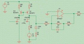
Edit, attached a quick job on Werners schematic, showing instead of the folded cascode a current mirror with an option to increase the current gain of the circuit above that of the J-Fet.... The input CTRL on the second FET should adjust the current for 0V on the output (servo).
The ratio between the resistor in the current mirror should probably be around 5, not 10 as shown, this would give around 150mA/V effective transconductance which with 750Ohm load gives around 41db gain, the OPA627 stage will then give 19db gain for a total gain of 60db overall.
Switching the resistors in the Current Mirror and in the source of the second (current source) FET would accomodate a gain adjustment for use with MM Pickups as well....
Werner said:It's too quiet in here, therefore I present this conceptual diagram of a phonostage I am working on.
This one has been dormant a good while, but it's probably worth resurrecting....
Here maybe a hint (you might know the source of this)....
First, the whole circuit inverts polarity.
What you could do is to scale the 3180/318uS part of the RIAA a little, so that you end up with 68K//47n & 6K8. Then use a 750R resistor to the INVERTING input and you have around 20db gain inverting and a 750R load on the preceeding stage.
You would probably need to parallel around 4 2SK170, but you would then get around 40db gain in the frontend. Slightly rearrange the cascode to use a negative supply to give near 0V on the output (servo controlled CCS?) and you should have somthing quite unique....
Then the circuit no longer inverts polarity and it owes a lot to a certain famoust Phonostage, but without the added complexity of a rail symmetric folded cascode.
Sayonara
Edit, attached a quick job on Werners schematic, showing instead of the folded cascode a current mirror with an option to increase the current gain of the circuit above that of the J-Fet.... The input CTRL on the second FET should adjust the current for 0V on the output (servo).
The ratio between the resistor in the current mirror should probably be around 5, not 10 as shown, this would give around 150mA/V effective transconductance which with 750Ohm load gives around 41db gain, the OPA627 stage will then give 19db gain for a total gain of 60db overall.
Switching the resistors in the Current Mirror and in the source of the second (current source) FET would accomodate a gain adjustment for use with MM Pickups as well....
Attachments
Konnichiwa Ogiers San,
All credit to JC, really interresting stuff he does in the Vendetta Phono....
I have also considered the standard variant you showed.
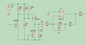
If we make the input resistor 5k1 (and EQ capacitor 15nF) and scale the feedback EQ network to 510K//6n2 and 51K we get a little more noise than the self noise of the OPA627 but we get the gain we need using just one 30mA/V Yfs J-FET (2 SK170 etc).
We can than use a 4.7uF coupling capacitor between cascode and Op-Amp which is still managable in terms of size/cost as film capacitor.
The EQ should be "close enough" at 3162/316.2/76.5uS, if we parallel 270K to the 5K1 input resistor we get the exact 75uS....
Then we get the attached....
We may need to adjust R8 to get the DC operating conditions of the cascode right and as said parallel 270K to R1.
For a MM Version I suspect the frontend has insuffucient headroom to use just the series resistor, so some additional form of switching may be needed to handle that.
Sayonara
Werner said:of course I know where your interpolation comes from ;-)
All credit to JC, really interresting stuff he does in the Vendetta Phono....
Werner said:The current mirror variant is interesting. The design space expands ...
I have also considered the standard variant you showed.
If we make the input resistor 5k1 (and EQ capacitor 15nF) and scale the feedback EQ network to 510K//6n2 and 51K we get a little more noise than the self noise of the OPA627 but we get the gain we need using just one 30mA/V Yfs J-FET (2 SK170 etc).
We can than use a 4.7uF coupling capacitor between cascode and Op-Amp which is still managable in terms of size/cost as film capacitor.
The EQ should be "close enough" at 3162/316.2/76.5uS, if we parallel 270K to the 5K1 input resistor we get the exact 75uS....
Then we get the attached....
We may need to adjust R8 to get the DC operating conditions of the cascode right and as said parallel 270K to R1.
For a MM Version I suspect the frontend has insuffucient headroom to use just the series resistor, so some additional form of switching may be needed to handle that.
Sayonara
Attachments
- Status
- This old topic is closed. If you want to reopen this topic, contact a moderator using the "Report Post" button.
- Home
- Source & Line
- Analogue Source
- folded-cascode FET/opamp MC phono