Ultra high spec. opamp MC/MM phono, warp "elliptic" filter, line, headphone amps.
This is a project that has been on Audio Karma for about a year and has had a number of revisions, additions and upgrades.
There are about 150 of the units in various versions out in the field and it was repeatedly suggested by builders that a thread be opened in DIYaudio- so despite some reluctance here it is.
As the title suggests, it is opamp based, and is hardly unique, but it has some unusual features and has stellar specs and is pretty easy to build.
Some features:
1. Optional parallel input amps-
2x LT1115/AD797/OPA1611 or OPA1612 for MC
2x OPA1641 or similar or OPA1656/OPA1642 for MM
Cartridge load components can be altered without soldering.
2. 75us TC in input stage to optimize overload characteristic- approx. 28dB at rated -9dBv output at all frequencies up to greater than 50kHz with +/-15v supplies.
3. Additional standard RIAA TCs in output stage.
4. Gain partitioning/opamp choices made to keep negative feedback factor high over the entire audio range to minimize high order harmonics and many tone IM distortion.
5. Interstage TC added to compensate for the transition to unity gain of the input gain stage to maintain RIAA characteristic compliance. No unity gain transition in output stage due to choice of architecture.
6. DC offset correction in the phono output- so no coupling caps.
7. Polypropylene caps used in all of the signal paths.
8. Off the shelf SMPS used with input LC filter.
7. Extensive on board power supply decoupling.
8. MC and MM versions can be built with some component changes.
FET input opamps for MM version. Bipolar for MC.
9. 62dB gain for standard MC stage, 42dB for MM. Nominal sensitivity- 250uv @1kHz, 5cm/sec for the MC, 2.5mv for the MM.
10. RIAA simulated compliance c. 20mdB p-p, 20Hz-20kHz. Measured with non selected off the shelf components to be <50mdB p-p. Simulated worst case <100mdB p-p.
11. Unmeasurably low (limited by measurement system) distortion at rated output, including harmonic and many tone.
12. Phono Warp first order "elliptic" filter with vertical (L-R) rejection of c. 3dB at 140Hz and c. 36dB at 2Hz. Nominally 0dB rejection of horizontal (L+R) rejection.
12. Additional 10dB gain can be selected in the warp filter section to increase overall gain to 72dB/52dB.
13. Buffers for volume control and line driving added, 47 ohm output impedance.
14. Mono switch, no balance control.
15. Optional balanced output drive, 47 ohms/side.
16. Optional (separate board) OPA1656/LMH6321 headphone amp. On board heatsinking. Can drive loads as low as 16 ohms. Unmeasurably low distortion. Output impedance c.0.1ohms. 6dB gain.
Measurement system. RME ADI-2 PRO FS R with REW.
High quality boards available. Schematics, measurement results, BOM and build guides available.
Any interest?
This is a project that has been on Audio Karma for about a year and has had a number of revisions, additions and upgrades.
There are about 150 of the units in various versions out in the field and it was repeatedly suggested by builders that a thread be opened in DIYaudio- so despite some reluctance here it is.
As the title suggests, it is opamp based, and is hardly unique, but it has some unusual features and has stellar specs and is pretty easy to build.
Some features:
1. Optional parallel input amps-
2x LT1115/AD797/OPA1611 or OPA1612 for MC
2x OPA1641 or similar or OPA1656/OPA1642 for MM
Cartridge load components can be altered without soldering.
2. 75us TC in input stage to optimize overload characteristic- approx. 28dB at rated -9dBv output at all frequencies up to greater than 50kHz with +/-15v supplies.
3. Additional standard RIAA TCs in output stage.
4. Gain partitioning/opamp choices made to keep negative feedback factor high over the entire audio range to minimize high order harmonics and many tone IM distortion.
5. Interstage TC added to compensate for the transition to unity gain of the input gain stage to maintain RIAA characteristic compliance. No unity gain transition in output stage due to choice of architecture.
6. DC offset correction in the phono output- so no coupling caps.
7. Polypropylene caps used in all of the signal paths.
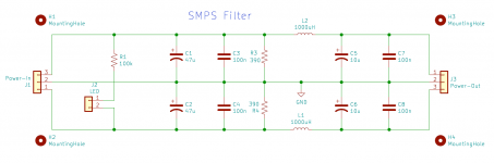
8. Off the shelf SMPS used with input LC filter.
7. Extensive on board power supply decoupling.
8. MC and MM versions can be built with some component changes.
FET input opamps for MM version. Bipolar for MC.
9. 62dB gain for standard MC stage, 42dB for MM. Nominal sensitivity- 250uv @1kHz, 5cm/sec for the MC, 2.5mv for the MM.
10. RIAA simulated compliance c. 20mdB p-p, 20Hz-20kHz. Measured with non selected off the shelf components to be <50mdB p-p. Simulated worst case <100mdB p-p.
11. Unmeasurably low (limited by measurement system) distortion at rated output, including harmonic and many tone.
12. Phono Warp first order "elliptic" filter with vertical (L-R) rejection of c. 3dB at 140Hz and c. 36dB at 2Hz. Nominally 0dB rejection of horizontal (L+R) rejection.
12. Additional 10dB gain can be selected in the warp filter section to increase overall gain to 72dB/52dB.
13. Buffers for volume control and line driving added, 47 ohm output impedance.
14. Mono switch, no balance control.
15. Optional balanced output drive, 47 ohms/side.
16. Optional (separate board) OPA1656/LMH6321 headphone amp. On board heatsinking. Can drive loads as low as 16 ohms. Unmeasurably low distortion. Output impedance c.0.1ohms. 6dB gain.
Measurement system. RME ADI-2 PRO FS R with REW.
High quality boards available. Schematics, measurement results, BOM and build guides available.
Any interest?
Last edited:
")
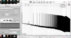
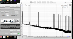
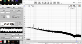
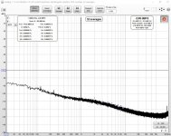
Some measurements, both of the phono stage alone, plus full preamp, plus full preamp with external passive remote controlled volume control/input selector.
Attachments
-
 12dBabove RO402equispacedtones.PNG237.9 KB · Views: 315
 -
 12dbaboveratedoutput.PNG249.6 KB · Views: 298
 -
 noinput.PNG245.8 KB · Views: 305
 -
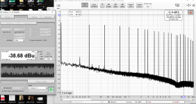 3dBbelowclipping.PNG239.5 KB · Views: 366
 -
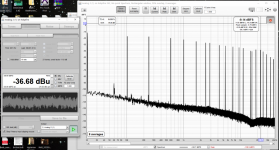 1dBbelowclipping.PNG256.3 KB · Views: 2,344
 -
 fullpreamp20ohmssource250uvip.JPG77.7 KB · Views: 2,403
 -
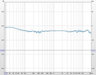 RCHRIAAavesmooth32mDBp-p.JPG54.7 KB · Views: 2,405
 -
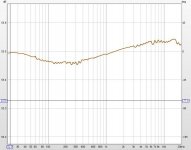 LCHRIAAAVSMOOTH82mdBp-p.JPG53.4 KB · Views: 2,480
Last edited:
I assume that it just acts on the L-R component?I've got a second order elliptical waiting to be built. I think they are a good idea for vinyl replay.
I started out with a second order, but found it hard to ensure acceptable frequency response flatness in the L+R channel when it was in use, and as that was against the philosophy of the design I decided to stick with a first order.
I find it has some value with the very few warped records that I have, but otherwise not so much.
Hi Wyn, I'd like to ask about your inductors in the supply filter (L1, L2 below).
From the 3D render of the circuit board, it appears you're using small radial-lead inductors roughly similar to the Bourns RLB0608-102KL. 1mH inductors in those sized packages usually have a self resonant frequency somewhere between 300 kHz and 3 MHz ; the Bourns datasheet for example says 1.8 MHz. I'd like to ask whether you think it's a good idea to specifically damp out that resonance, both from a nothing-but-the-best perspective and also from a cost-versus-benefit perspective. And whether you believe it is significant or insignificant that "ultra high spec opamps" have plenty of gain, but greatly diminished PSRR, at 2 MHz.
Thanks very much!
_
Attachments
It's not my design, as I had dismissed them for similar reasons, but Wayne Kirkwood did one for vinyl mastering. Getting the allpass right is the trick. If I build it fully I can select 300/150/75Hz roll off but its a lot of extra parts. On current rate of completion won't be until 2022 I get to start building it...
I actually built a model with the resonances associated with the external filter components and the on board filter networks and simulated the design up to several MHz. The model included the SRFs of the decoupling caps (c. 300kHz for the electrolytics if I remember correctly, and 2.2MHz for the WIMA 0.1uF PP caps, with an ESR in the order of 10mohm.). The SMPS supply to output response was simulated using the opamp behavioral models, and the SMPS to the supply terminal was also examined. I don't remember any particularly egregious issues.Hi Wyn, I'd like to ask about your inductors in the supply filter (L1, L2 below).
From the 3D render of the circuit board, it appears you're using small radial-lead inductors roughly similar to the Bourns RLB0608-102KL. 1mH inductors in those sized packages usually have a self resonant frequency somewhere between 300 kHz and 3 MHz ; the Bourns datasheet for example says 1.8 MHz. I'd like to ask whether you think it's a good idea to specifically damp out that resonance, both from a nothing-but-the-best perspective and also from a cost-versus-benefit perspective. And whether you believe it is significant or insignificant that "ultra high spec opamps" have plenty of gain, but greatly diminished PSRR, at 2 MHz.
Thanks very much!
_
You need to look at the situation as a whole. firstly, how much residual 1.8MHz plus noise exists at the output of a SMPS with a switching rate of c. 80kHz. Measurements of broadband noise up to 192kHz (the limits of my digital system) suggests extremely little.
Secondly, if I remember correctly the equivalent series resistance of the inductance is in the order of a few ohms and the shunt capacitance in the order of 10pF. This cap is then loaded with local decoupling (including the 0.1uF caps mentioned before) and is then applied to the phono stage board where is goes through two in line R (10 ohm)-C (Pi network between the rails) filter stages before being applied to the input opamp, and a single identical network before being applied to the output opamps. The attenuation ratio is quite high, and in reality is probably more limited, prior to the wima caps resonance, by the board resistances.
Above 2.2MHz? Sorry, but I say that I really care. There's no evidence of any noise being folded back into the audio band that I can see- particularly since the noise characteristic appears to be source agnostic insofar as I've operated it with batteries, linear supplies etc. with no measurable difference in the audio band.
The "elliptic" filter employed by cutting lathes used to be a simple RLR network, and that defined the L+R/L-R relationship of the bass. In general I believe it is assumed that the "conversion" is valid up to 200Hz or so, but it's a first order characteristic, and as far as i know there's no actual detailed spec.It's not my design, as I had dismissed them for similar reasons, but Wayne Kirkwood did one for vinyl mastering. Getting the allpass right is the trick. If I build it fully I can select 300/150/75Hz roll off but its a lot of extra parts. On current rate of completion won't be until 2022 I get to start building it...
So, what is the purpose of the phono warp "elliptic" filter- it's to eliminate (?) the presence of L-R signals in the region up to 200Hz or so caused by vertical displacements of the stylus. However, there's conversion of vertical information to L+R if the displacement isn't entirely vertical, and also if the channel separation and alignment in the cartridge isn't perfect.
It's unclear to me that a more complex, phase corrected 2nd order network (like the one I originally started to construct) will actually result in a superior outcome when all you hope for is (at least in my mind) a reduction in woofer excursion and the whump of the warp without too egregiously damaging the stereo signal with its undefined frequency boundary.
This may be incorrect, but in the absence of evidence to the contrary I elected to abandon the higher order approach and go with a simple to implement 1st order design.
I've spent a little time pondering the second part of your question to try and come up with an opinion/ explanation- but I've no idea if this will be helpful and I have no knowledge of your technical expertise.Hi Wyn, I'd like to ask about your inductors in the supply filter (L1, L2 below).
From the 3D render of the circuit board, it appears you're using small radial-lead inductors roughly similar to the Bourns RLB0608-102KL. 1mH inductors in those sized packages usually have a self resonant frequency somewhere between 300 kHz and 3 MHz ; the Bourns datasheet for example says 1.8 MHz. I'd like to ask whether you think it's a good idea to specifically damp out that resonance, both from a nothing-but-the-best perspective and also from a cost-versus-benefit perspective. And whether you believe it is significant or insignificant that "ultra high spec opamps" have plenty of gain, but greatly diminished PSRR, at 2 MHz.
Thanks very much!
_
Data sheet PSRR for opamps is generally defined relative to the input- that is the gain from the input to the output (in dBs) divided by the gain from the supply to the output (in dBs)
In other words- change the supply by 1v, say, at the measurement frequency, with the differential input set to zero. Measure the output change relative to the supply change, express it in dBs, negate it, then add the open loop gain of the opamp at that frequency in dBs and the result is the data sheet PSRR at that frequency expressed in dBs.
This means that there is sort of an "intrinsic" PSRR vs frequency due to the circuit design details- and the potential action of negative feedback is presumed to cause the effective PSRR to increase as the frequency falls.
Thus the actual operational PSRR is a function of the feedback factor, that is the ratio of open loop gain to closed loop gain at a given frequency, and the "intrinsic" PSRR. i.e. effective PSRR= (mainly) data sheet PSRR (dB)- closed loop gain (dB).
If the correction due to the feedback factor becomes lower than the "intrinsic" PSRR then the PSRR will remain equal to the "intrinsic" PSRR even though the open loop gain continues to fall.
So, the optimal approach to PSRR optimization is to select a closed loop gain and roll it off at a frequency where it remains adequate to the desired set of goals, including PSRR.
Looking at the PSRR of, say, the OPA1611 shows something interesting.
The PSRR falls monotonically at 6dB/octave until about 10MHz (the open loop gain is about 18dB), when it falls at c. 12dB/octave. The PSRR shows something similar- except it becomes constant (at about 18dB) at about the frequency where the compensation scheme changes, even though the open loop gain is falling. This implies that the intrinsic PSRR has remained constant in that region and is no longer dependent on feedback.
So, the bottom line is. Don't have too high a closed loop gain- which is also a good thing as far as having enough feedback to ensure high order harmonic distortion is adequately small is concerned- have the bandwidth rolled off, select an opamp with as decent an "intrinsic" PSRR as you can, and design the supply and decoupling networks to be as quiet as possible at HF.
I hope that this is at least reasonably coherent...
"The PSRR falls monotonically at 6dB/octave until about 10MHz (the open loop gain is about 18dB), when it falls at c. 12dB/octave. The PSRR shows something similar- except it becomes constant (at about 18dB) at about the frequency where the compensation scheme changes, even though the open loop gain is falling. This implies that the intrinsic PSRR has remained constant in that region and is no longer dependent on feedback."
Typo:
it should be "open loop gain" instead of PSRR in the first sentence.
I can't seem to find out how to edit my posts.
Is there a time limit?
Typo:
it should be "open loop gain" instead of PSRR in the first sentence.
I can't seem to find out how to edit my posts.
Is there a time limit?
My own personal preference, especially in DIY gear whose goals don't include "price competitiveness", is to simply install the damping resistor. This completely eliminates the inductor self resonance. Kill it till it's good and dead: then it can't possibly bother you later. The cost (one extra resistor) is small, while the benefit (peace of mind) is large.
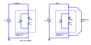
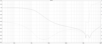
I looked up the parameters of the Bourns 1000uH inductor mentioned previously, and put it into a simulation both WITH, and also WITHOUT, a damping resistor "Rcalmdown".
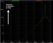
Without Rcalmdown, the inductor's impedance peaks fairly dramatically at the self resonant frequency, 1.8 MHz. With Rcalmdown, the impedance curve is nice and smooth. We are of course delighted to see that Rcalmdown does not change the inductor's response AT ALL, across the SMPS noise frequencies we're most interested in: 10 kHz to 300 kHz. It tames the peak but otherwise stays out of the way. Aaaaaahhhh.
All that for the price of one resistor? Sign me up.
_
I looked up the parameters of the Bourns 1000uH inductor mentioned previously, and put it into a simulation both WITH, and also WITHOUT, a damping resistor "Rcalmdown".
Without Rcalmdown, the inductor's impedance peaks fairly dramatically at the self resonant frequency, 1.8 MHz. With Rcalmdown, the impedance curve is nice and smooth. We are of course delighted to see that Rcalmdown does not change the inductor's response AT ALL, across the SMPS noise frequencies we're most interested in: 10 kHz to 300 kHz. It tames the peak but otherwise stays out of the way. Aaaaaahhhh.
All that for the price of one resistor? Sign me up.
_
Attachments
My own personal preference, especially in DIY gear whose goals don't include "price competitiveness", is to simply install the damping resistor. This completely eliminates the inductor self resonance. Kill it till it's good and dead: then it can't possibly bother you later. The cost (one extra resistor) is small, while the benefit (peace of mind) is large.
I looked up the parameters of the Bourns 1000uH inductor mentioned previously, and put it into a simulation both WITH, and also WITHOUT, a damping resistor "Rcalmdown".
Without Rcalmdown, the inductor's impedance peaks fairly dramatically at the self resonant frequency, 1.8 MHz. With Rcalmdown, the impedance curve is nice and smooth. We are of course delighted to see that Rcalmdown does not change the inductor's response AT ALL, across the SMPS noise frequencies we're most interested in: 10 kHz to 300 kHz. It tames the peak but otherwise stays out of the way. Aaaaaahhhh.
All that for the price of one resistor? Sign me up.
_
So, what if a series decoupling element has a series resonance?
That simply means that the rejection of the filter is maximized at that point. The SMPS doesn't use the filter as part of its output network. There already is a shunt Rq due to the finite Q of the inductor- 50 at 0.252MHz- but that's in the Mohm range. Why put in a shunt R to reduce the rejection peak? Of more concern is what happens after resonance, when the impedance transforms to capacitive and the rejection falls.
Of additional concern, in my opinion, is the resonance of the inductor with the decoupling caps. I sometimes add loss to the "output" to tame that.
By the way, the actual specified component is the RLB0913-102k, which has a SRF of 1.3MHz, and 2.35 DC res.
I'll try to dig up the simulation files- assuming I still have them- and post the full transfer characteristic.
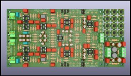
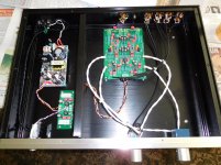
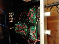
For those curious what a completed unit looks like, this is an earlier version I built last year, without the headphone amp board or built-in warp filter. It was on display at the 2019 BAF.
Below is the latest prototype build with warp filter and headphone.
The board shown earlier has all but the headphone amp.
As is the case with prototypes, it's a bit messy but it works beautifully.
Attachments
My own personal preference, especially in DIY gear whose goals don't include "price competitiveness", is to simply install the damping resistor. This completely eliminates the inductor self resonance. Kill it till it's good and dead: then it can't possibly bother you later. The cost (one extra resistor) is small, while the benefit (peace of mind) is large.
I looked up the parameters of the Bourns 1000uH inductor mentioned previously, and put it into a simulation both WITH, and also WITHOUT, a damping resistor "Rcalmdown".
Without Rcalmdown, the inductor's impedance peaks fairly dramatically at the self resonant frequency, 1.8 MHz. With Rcalmdown, the impedance curve is nice and smooth. We are of course delighted to see that Rcalmdown does not change the inductor's response AT ALL, across the SMPS noise frequencies we're most interested in: 10 kHz to 300 kHz. It tames the peak but otherwise stays out of the way. Aaaaaahhhh.
All that for the price of one resistor? Sign me up.
_
I found one of the sims.
Attachments
Last edited:
- Home
- Source & Line
- Analogue Source
- Ultra high spec opamp MC/MM phono, warp "elliptic" filter, line, headphone amps