This thread is about the hifisonix X-Altra MC/MM Phono EQ Preamplifier published in audioXpress in February and March of 2021. The design uses separate circuits for the MC and MM stages in order to optimise the noise performance amongst other parameters. On MC input, the measured 1kHz spot noise (full MC + MM signal chain) was under 250pV/rt Hz, while on MM inputs with a 1350 Ohm + 500 Ohm cartridge source, the SNR is specified at >76 dB unweighted, and >80 dB 'A' weighted. On both MC and MM inputs, the overload margin across the audio band exceeds 30 dB (see the specifications below). The X-Altra MC/MM makes extensive use of SMD components.
Below are the links to Part 1 and 2 of the articles as printed in audioXpress
Part 1 of the article https://audioxpress.com/files/attachment/2735
Part 2 https://audioxpress.com/files/attachment/2736
For supplementary information like BOM, measurement technique etc, follow this link Russell-XAltra-AX-Feb2021
You can buy a PCB set (main signal board plus rear panel board) for US$49.50 + $15 tracked shipping - details on the web page below.
Link to the hifisonix X-Altra MC/MM page https://hifisonix.com/x-altra-phono-eq-preamp/
Here it is on Pinterest courtesy audioXpress https://www.pinterest.co.uk/pin/you-can-diy-xaltra-mcmm-riaa-eq-preamp-part-1--733875701785808118/
Here's the link to Andy Lowe's excellent set of measurements on his build fireanimal's independent measurements and more measurements here
Here's the link to his build photos fireanimal's X-Altra MC/MM build
As always, if you have any questions, or need help with your build, just ping me.
ERRATUM
C9 and C25 on the circuit diagram are shown the wrong way around. PCB's shipped after July 2020 had the component orientation corrected. So, follow the PCB silkscreen which is correct.
Finally, here are the X-Altra MC/MM specifications. Kindly note these specifications were all confirmed with measurements using the QA401. As a comparative indicator of noise performance, the MM 1 kHz spot noise (measured) >8 dB better than the OPA1652 and >10 dB better than the OPA1642. Compared to MC preamplifiers using the AD797 low noise opamp, the X-Altra MC RTI MM 1 kHz spot noise is 11.7dB quieter (0.232V/rt Hz vs .9nV/rt Hz) - this is the whole signal chain performance, so from the MC input right through to the output of the preamplifier. The 1/f noise on the X-Altra MC/MM is also substantially lower, and the knee frequency is well below 100 Hz, a trick IC-based front-end MM stages are unable to replicate. On MC input, the X-Altra offers just about the lowest noise of any commercial or DIY preamp, and on MM, it's at the theoretical limit when considering performance with a cartridge connected; on both input types, the outstanding noise performance comes with >30 dB overload capability from <20 Hz to 50 kHz.


Here are some independent measurements of various JFET's (courtesy MV Audio Labs)
Below are the links to Part 1 and 2 of the articles as printed in audioXpress
Part 1 of the article https://audioxpress.com/files/attachment/2735
Part 2 https://audioxpress.com/files/attachment/2736
For supplementary information like BOM, measurement technique etc, follow this link Russell-XAltra-AX-Feb2021
You can buy a PCB set (main signal board plus rear panel board) for US$49.50 + $15 tracked shipping - details on the web page below.
Link to the hifisonix X-Altra MC/MM page https://hifisonix.com/x-altra-phono-eq-preamp/
Here it is on Pinterest courtesy audioXpress https://www.pinterest.co.uk/pin/you-can-diy-xaltra-mcmm-riaa-eq-preamp-part-1--733875701785808118/
Here's the link to Andy Lowe's excellent set of measurements on his build fireanimal's independent measurements and more measurements here
Here's the link to his build photos fireanimal's X-Altra MC/MM build
As always, if you have any questions, or need help with your build, just ping me.
ERRATUM
C9 and C25 on the circuit diagram are shown the wrong way around. PCB's shipped after July 2020 had the component orientation corrected. So, follow the PCB silkscreen which is correct.
Finally, here are the X-Altra MC/MM specifications. Kindly note these specifications were all confirmed with measurements using the QA401. As a comparative indicator of noise performance, the MM 1 kHz spot noise (measured) >8 dB better than the OPA1652 and >10 dB better than the OPA1642. Compared to MC preamplifiers using the AD797 low noise opamp, the X-Altra MC RTI MM 1 kHz spot noise is 11.7dB quieter (0.232V/rt Hz vs .9nV/rt Hz) - this is the whole signal chain performance, so from the MC input right through to the output of the preamplifier. The 1/f noise on the X-Altra MC/MM is also substantially lower, and the knee frequency is well below 100 Hz, a trick IC-based front-end MM stages are unable to replicate. On MC input, the X-Altra offers just about the lowest noise of any commercial or DIY preamp, and on MM, it's at the theoretical limit when considering performance with a cartridge connected; on both input types, the outstanding noise performance comes with >30 dB overload capability from <20 Hz to 50 kHz.
Here are some independent measurements of various JFET's (courtesy MV Audio Labs)
Last edited:
Hello, the X-Altra MC/MM RIAA EQ Preamplifier will be published in 2 parts, the first being in the February issue of audioXpress and the 2nd in March.
All supplementary info (assembly instructions, BOM, user manual, specifications etc) will be hosted by audioXpress.
If anyone is interested in getting boards, these will be available AFTER the 2nd part of the article in March.
All supplementary info (assembly instructions, BOM, user manual, specifications etc) will be hosted by audioXpress.
If anyone is interested in getting boards, these will be available AFTER the 2nd part of the article in March.
AudioExpress support purchase the pdf,this is gread for us.
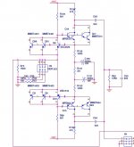
@Russell,I have some quesitons for the figure 5.
1. In LEFT MC Head Amp block,the label Left MC means for the MC Head Amp output,right?that connect to the MM input and MC Amplifier Servo block MC In L label and the LZERO connect the Servo block LZERO,is that correct?
2. in the Low Noise MC Power Supply block,does the -5 and +5 label need another +-5V power supply? or it provide +-5V power for other block. and where is the V+10ref label from?
any comments will be great appreate.
BR
Leo
An interesting read and design so far for the phonograph enthusiast. Enlightening to see one persons design and implementation. The MC design looks to be rather low cost compared to some that I have seen using multiple jfets. Kinda reminds me of the PLR design, using the complementary common base arrangement
I see a face to a name, cheers mate
Rick
I see a face to a name, cheers mate
Rick
It was in an old AX article = copyrighted material.
I had a design using it, it was never made so not sure how well it works. I was using dual footprints so it is not exactly as it was originally drawn.
But this thread is about the X-Altra phono design, a much refined and tested design, not about the PLR design.
Kind of hard to discuss a design that not everyone has made available to themselves.
Attachments
Last edited:
An interesting read and design so far for the phonograph enthusiast. Enlightening to see one persons design and implementation. The MC design looks to be rather low cost compared to some that I have seen using multiple jfets. Kinda reminds me of the PLR design, using the complementary common base arrangement
I see a face to a name, cheers mate
Rick
")
What I did with this design is used circuits optimized for the source impedance so the MC and MM input circuits are different.
The MC noise floor is very low at < 250 PV/rt Hz (measured). The challenge with JFET’s is the noise voltage is high, so you have parallel many of them (15-20) to get similar noise performance on lo Z source inputs like a MC generator and that’s expensive. OTOH for MM, they are a better choice. Using a LSK389 with both devices paralleled, above about 800 ohms the device thermal noise approaches that of an ideal resistor. IOW, the excess noise is all below 800 Hz.
Last edited:
I read and understand that the low 'rbb bjts (Zetex/Diodes) are the correct devices or best economical solution to use in this MC design case. The jfets for higher source Z where the current noise in the bjts become dominate.
I have been looking at Samuel Groner's LN lab amp, Bob's Vinyl Trak, syn08's designs, all interesting.
Your design is so much simpler IMO and gets the job done
The schematic was a bit confusing, even for me some folks are not used to seeing ports and net names making connections across pages or ascending hierarchy
we are preparing an AX article, but the schematics were all re-drawn in Visio to be put in the word doc. My large Orcad drawing on a "C" sheet just won't work in print very well
I have been looking at Samuel Groner's LN lab amp, Bob's Vinyl Trak, syn08's designs, all interesting.
Your design is so much simpler IMO and gets the job done
The schematic was a bit confusing, even for me
some folks are not used to seeing ports and net names making connections across pages or ascending hierarchywe are preparing an AX article, but the schematics were all re-drawn in Visio to be put in the word doc. My large Orcad drawing on a "C" sheet just won't work in print very well
Last edited:
- Home
- Source & Line
- Analogue Source
- Bonsai’s X-Altra MC/MM Phono Preamp