There can be plenty of good reasons to apply cascoding, but worrying about Miller effect increasing the input capacitance is not one of them when there is already an overall feedback loop preventing that.
When you want to know how it works out for other configurations than those in the document, the trick is to figure out what signal voltages occur on the gates and drains under closed-loop conditions. Once you know that, you can calculate what signal current flows through the gate-drain capacitances under closed-loop conditions.
When you want to know how it works out for other configurations than those in the document, the trick is to figure out what signal voltages occur on the gates and drains under closed-loop conditions. Once you know that, you can calculate what signal current flows through the gate-drain capacitances under closed-loop conditions.
Take a look at this preamp as it is very similar in the input(actually many preamps heve the same input with your Denon including the APT Holman preamp) but has pretty good reviews .It also have the mc pre pre which is not bad at all.Dreamth: Thanks for all advice on the Denon...
I am still looking for that "ideal" two stage MM RIAA design where both current noise and voltage noise is low enough so that RIAA noise is well below record surface noise independently of high impedance/inductive cartridges are used or if using low impedance High Output MC cartridges.
I have a Fisher ca 2030 whose preamp i wanted to mod back to the original cc 3000, but i just did other things in the mean time.
Fisher CC-3000 Stereo Control Amplifier Manual | HiFi Engine
FISHER CC-3000 SCHEMATIC Service Manual download, schematics, eeprom, repair info for electronics experts
I'd also like if you can send me, please, the service manual as i can't acces Hi-fi engine from my country!
Last edited:
I'd also like if you can send me, please, the service manual as i can't acces Hi-fi engine from my country!
PM sendt
OK, I was thinking of opening a new thread for RIAA preamps, discrete and IC, and perhaps it might be more useful to hijack this thread, if you allow me.
What I would like to propose is to upload some LTSpice simulations that I have been doing for some time, with several designs taken from many sources.
As this is DIY, and I guess clones are part of it, let's hope it's alright and the original designers do not come complaint here.
The designs I simulated were:
1) Luxman MM clone design, with different active parts than the original. So I'm not sure you can call it a clone.
2) Gary Galo's mod of an Adcom RIAA preamp published on an electronics magazine. The original Adcom design was based on an LT1115 datasheet proposed RIAA design, which Galo modified with AD745 on first stage.
3) Discrete Elektor design based preamp, using modern transistors.
4) Variations on an LM4562 datasheet proposed design for a RIAA preamp. I swapped different ICs and got important improvements on the sims.
If you are interested and are familiar with LTSpice, then I can upload the asc files. Or if you think so I can open a new thread.
It's part of this project to add DC servo and high quality regulators, like Jung's.
There are some other things I would like to try which I would like some opinions of.
Last edited:
If you can't open the schematics I will upload them, one by one.
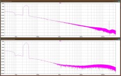
I also enclosed a simulation THD comparison on the LT/Adcom design, interchanging the first chip: the AD745 and the LT1792. Both are FET opamps, both are low noise, but the price is quite different.
If you play with the simulations in LTSpice you will find interesting results.
The only ones I have listened to in this bunch are the Luxman discrete, which is superb, and the SLN, an old Elektor discrete design which is not this version.
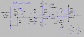
An interesting and simple design is the one I called LT1792 RIAA preamp, which is based on the LM4562 original preamp proposed by National, but which gets much better specs with these LT chips. You may notice it doesn't have a DC servo, but I am not sure offset will be really close to zero as the sim shows.
Comments and critics are welcome.
I also enclosed a simulation THD comparison on the LT/Adcom design, interchanging the first chip: the AD745 and the LT1792. Both are FET opamps, both are low noise, but the price is quite different.
If you play with the simulations in LTSpice you will find interesting results.
The only ones I have listened to in this bunch are the Luxman discrete, which is superb, and the SLN, an old Elektor discrete design which is not this version.
An interesting and simple design is the one I called LT1792 RIAA preamp, which is based on the LM4562 original preamp proposed by National, but which gets much better specs with these LT chips. You may notice it doesn't have a DC servo, but I am not sure offset will be really close to zero as the sim shows.
Comments and critics are welcome.
Attachments
Three comments:
1. It would be nice if you could also include schematics that are readable without LTSpice.
2. A DC feedback loop across a RIAA equalized amplifier shifts the poles, so you have to place them at other locations than normal to get them where you want after closing the DC loop. Maybe you already did that or found an implementation where it is no issue - I haven't a clue because I have no access to LTSpice at the moment.
3. Noise simulations and measurements only produce sensible results when you include the cartridge inductance, otherwise you grossly underestimate the effect of the input noise current. Maybe you already took that into account, I haven't a clue because I have no access to LTSpice at the moment.
Let's start with the schematics for those that do not use LTSpice.
As you can see the basic circuit is the same, but the THD results in PSRR are interestingly different.
It's unlikely that I will try the AD745 version, as the chip is expensive and a bit tricky to solder for my inexperienced SMD hands.
But I do have some LT1115, which I can unplug and compare audio quality with the LT1792, easier solder on an SMD to DIP-8 adapter.
This design already included the DC servo in the Gary Galo mod, so the implementation should be correct.
Attachments
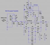
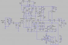
The first design is based on the Luxman 5C50 preamp. I don’t think you could actually call it a “clone” because all the active parts are different, including the dual input FET.
The other thing is that the original design was pure-DC, which mean it didn’t use a cap on the feedback or a DC Servo, though it did have an output film cap of 2.2uF. To achieve that Luxman certainly had the parts hand-selected at the factory or even from the manufacturer itself. That’s a luxury a regular DIYer will not have, and not selecting the parts, even if zeroing the offset with the trimpot, will mean you will need a feedback cap or a DC servo.
In my case I have a friend who owns a 5C50, so I can compare my clone to the original Luxman design, and see if the DC-servo affects audio quality. As I will have to design a pcb for this preamp, I will provide space for a feedback cap too.
On the simulation, THD and offset with the clone were the following:
1) With DC Servo: THD 0.000359%; DC offset 2uV
2) Without DC Servo: THD 0.000362%; DC offset 622mV (too high)
3) With 470uF feedback cap: THD 0.000362%; DC offset 1mV (acceptable)
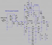
The following schematic is based on the original RIAA preamp proposed by National for their LM4562. Let’s mention that my simulation findings with the original National design using the LM4562 were an unacceptable high THD: 0.126%.
You can check that using the LT1792 simulation, and replacing the LTs with the LM.
THD with the LT1792 is 0.000418%, with no offset.
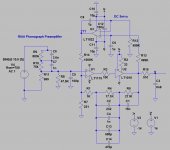
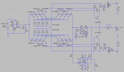
The SLN of the final BJT design goes for Super Low Noise. That had been an Elektor design from the early ‘80s, which originally used BC550/BC560 transistors. Elektor updated that design much later, but paralleling several AD797, which resulted in a very expensive preamp.
As the original transistors are hard to find, the proposed project uses modern low noise KSA and KSC transistors, not as low noise as the original but worth a try. A pcb will have to be designed for this project.
The other thing is that the original design was pure-DC, which mean it didn’t use a cap on the feedback or a DC Servo, though it did have an output film cap of 2.2uF. To achieve that Luxman certainly had the parts hand-selected at the factory or even from the manufacturer itself. That’s a luxury a regular DIYer will not have, and not selecting the parts, even if zeroing the offset with the trimpot, will mean you will need a feedback cap or a DC servo.
In my case I have a friend who owns a 5C50, so I can compare my clone to the original Luxman design, and see if the DC-servo affects audio quality. As I will have to design a pcb for this preamp, I will provide space for a feedback cap too.
On the simulation, THD and offset with the clone were the following:
1) With DC Servo: THD 0.000359%; DC offset 2uV
2) Without DC Servo: THD 0.000362%; DC offset 622mV (too high)
3) With 470uF feedback cap: THD 0.000362%; DC offset 1mV (acceptable)
The following schematic is based on the original RIAA preamp proposed by National for their LM4562. Let’s mention that my simulation findings with the original National design using the LM4562 were an unacceptable high THD: 0.126%.
You can check that using the LT1792 simulation, and replacing the LTs with the LM.
THD with the LT1792 is 0.000418%, with no offset.
The SLN of the final BJT design goes for Super Low Noise. That had been an Elektor design from the early ‘80s, which originally used BC550/BC560 transistors. Elektor updated that design much later, but paralleling several AD797, which resulted in a very expensive preamp.
As the original transistors are hard to find, the proposed project uses modern low noise KSA and KSC transistors, not as low noise as the original but worth a try. A pcb will have to be designed for this project.
Attachments
But I do have some LT1115, which I can unplug and compare audio quality with the LT1792, easier solder on an SMD to DIP-8 adapter.
Noise-wise, the LT1115 and LT1028 are about the worst op-amps on the market for moving magnet cartridges, with their equivalent input noise current of about 3.4 pA/sqrt(Hz) when measured with unequal impedances driving the positive and negative inputs.
The SLN of the final BJT design goes for Super Low Noise. That had been an Elektor design from the early ‘80s, which originally used BC550/BC560 transistors. Elektor updated that design much later, but paralleling several AD797, which resulted in a very expensive preamp.
The moving-magnet version of the Elektor Supra 2.0 uses four parallel LT1028 op-amps, which is even worse than using a single LT1028 (6.8 pA/sqrt(Hz) instead of 3.4 pA/sqrt(Hz)). Its current noise must be so horrible it isn't even masked by record surface noise anymore. The earlier, discrete amplifier is not exactly in the noise optimum, but it is not really bad like the 2.0.
The moving-magnet version of the Elektor Supra 2.0 uses four parallel LT1028 op-amps, which is even worse than using a single LT1028 (6.8 pA/sqrt(Hz) instead of 3.4 pA/sqrt(Hz)). Its current noise must be so horrible it isn't even masked by record surface noise anymore. The earlier, discrete amplifier is not exactly in the noise optimum, but it is not really bad like the 2.0.
I knew of a version using AD797s, not LT1028.
The pcb was very expensive.
You didn't comment anything on the LT1792 design, the simpler one, where I replaced the LM4562 in the simulation.
That's because I didn't know the LT1792 and was too lazy to look up its datasheet. I just looked it up and as far as I can tell, it's a very good choice for moving magnet amplifiers.
He, she or it tries to sell things: https://www.muffsy.com/
Anyway, for the noise simulations, you can model the cartridge as the series connection of the specified DC resistance and the specified self inductance of the cartridge, for example 1 kohm and 500 mH in series. It's an oversimplification because some cartridges have a series resistance that increases substantially with frequency, but it is enough to ensure you see the effect of the amplifier's noise current.
Anyway, for the noise simulations, you can model the cartridge as the series connection of the specified DC resistance and the specified self inductance of the cartridge, for example 1 kohm and 500 mH in series. It's an oversimplification because some cartridges have a series resistance that increases substantially with frequency, but it is enough to ensure you see the effect of the amplifier's noise current.
- Status
- Not open for further replies.
- Home
- Source & Line
- Analogue Source
- FET vs BJT input phono preamp