I'm just wondering here.. Those heatsinks for the fets are attached to the ground plane I think right? I've got screws through the holes in the PCB where the heatsink is.
I do have some thermal pads and also plastic shoulder washers which I think should keep the FETs isolated from the heatsinks, but are these symptoms looking like potentially somehow there isn't proper isolation between the FETs and the heatsinks?
I do have some thermal pads and also plastic shoulder washers which I think should keep the FETs isolated from the heatsinks, but are these symptoms looking like potentially somehow there isn't proper isolation between the FETs and the heatsinks?
I'm thinking I'm on to something here.. It seems as though there is only 28 ohms of resistance between the metal tab on Q1P and ground, whereas all the other FETs are showing 68Kohm, which honestly still seems bad to me.. I would have assumed these should all be reading really high. So I guess maybe I've used thermal pads that are not actually electrically isolating which is super annoying. Maybe I should go back and try to use some mica pads instead of these ones I ordered https://www.mouser.ca/ProductDetail/567-175-6-210P
I just hope I haven't gone and fried a bunch of stuff on this board now though...
EDIT: Nevermind, I guess I'm measuring 68K ohm to ground on the good fets because that IS what's in the circuit from the metal tab to ground, and on the one that is measuring 28ohm to ground, that's because I've fried some of the circuitry between that tab and ground.. It's not the isolation. I measure infinite between the metal tab and a bare metal section of the heatsink, so that's not what's going on.. Back to square one.
Last edited:
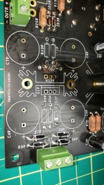
Well, I pulled out a bunch of components in that section of the power supply, and it would appear as though this board is getting to a point that I don't know if it's useable.. Man that sucks. I cleaned up the top after pulling some parts out, and you can see that the traces in one section appear to have actually blown out of the board now.
Still I cannot seem to find a single thing I did wrong. Quadruple checked component values, made sure all the solder points are good and there's no shorts anywhere.. I'm just at a loss
Still I cannot seem to find a single thing I did wrong. Quadruple checked component values, made sure all the solder points are good and there's no shorts anywhere.. I'm just at a loss
Attachments
Well, I figured one more thing out.. I had sort of partially blown a fuse on my AC line.. Very strange behavior. I measured the AC on my power transformers, and it was going up very gradually.. Which seems odd, so I pulled out the fuse and while it looked okay it measured 160K ohm.. So I'm guessing what happened is that there was not proper AC applied to the circuits when I powered it up this last time. I am surprised it blew up in such a spectacular fashion though. Would little or no AC cause something like this to happen?
I am trying to figure out if this board is still salvagable, with that one trace blown out like it is I'm just really not too sure.. I wonder what I would need to measure to determine whether there are any broken traces, or shorted traces anywhere..
I know that the schematic is not openly available for this. But is there any way I could be DM'd a portion of the schematic? For this power supply section? I am having a hard time seeing the traces and knowing what should be connected to what..
Last edited:
If I measure from R9P to R10P (following that one trace that connects it to R10P) I do measure 0 ohms, and from the other side of R9P I don't seem to measure any shorts to anywhere else that I can see.. A few measurements of 1M+ ohms, but that's it on that front. Is that what you mean?
Also, what trace do you think that is that blew out of the board? It's basically a big chunk of copper trace that was underneath R9P. Is it important that that have continuity? It seems like a part of that trace might be missing.
Also, what trace do you think that is that blew out of the board? It's basically a big chunk of copper trace that was underneath R9P. Is it important that that have continuity? It seems like a part of that trace might be missing.