Hi guys,
I'd like to ask your advise on this one.
I've built a ESP (Elliot's) P06 phono preamp recently.
While i tested with +/-15V DC power connected and everything else NOT connected (meaning the preamp is not connected to my turntable outputs and my amplifier inputs) i get negative 7mV DC voltage in the RCA inputs of the preamp.
I measured that by connecting my multimeter's red (positive) probe to the center conductor of the preamp RCA inputs and my multimeter's black (negative) probe to the outer conductor (ground) of the RCA inputs.
Is the presence of any voltage in the preamp inputs a normal thing?
I did the same test at the inputs and outputs of my Creek OBH-8SE preamp and voltage presence is nowhere to be found there.
I'm worried whether that voltage presence at the P06 preamp is normal, i don't want to risk my turntable's cartridge.
Thank you for your inputs.
Last edited:
If we are looking at fig 1
Hi-Fi RIAA Phono Preamp
Then yes, it is normal and due to the high bias current of the NE5532 flowing in R1 and R2 and developing a volt drop. The 5532 has particularly high bias currents.
So all normal.
Hi-Fi RIAA Phono Preamp
Then yes, it is normal and due to the high bias current of the NE5532 flowing in R1 and R2 and developing a volt drop. The 5532 has particularly high bias currents.
So all normal.
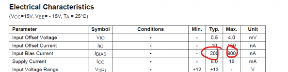
From an old Fairchild data sheet.
If you multiply the current shown here (there is no best or minimum case shown, just typical and maximum) then you will get the expected voltage across your resistor which in this case is 47k + 2k2.
Worst case for your values the voltage would be 40 millivolts. Ouch")
Typically it will 10 millivolts. So all good.
If you multiply the current shown here (there is no best or minimum case shown, just typical and maximum) then you will get the expected voltage across your resistor which in this case is 47k + 2k2.
Worst case for your values the voltage would be 40 millivolts. Ouch
Typically it will 10 millivolts. So all good.
Attachments
If the actual input were AC coupled then you wouldn't see that voltage. It is not really an issue because the voltage developed depends on the resistance present which is 49.2k in your case but that is without connecting to a cartridge.
The resistance of the cartridge will lower that voltage.
So if your cartridge has a resistance of (guessing as I don't know cartridge values) say 800 ohms then the voltages would fall to around 0.16 millivolts to 0.6 millivolts for those data sheet values of current.
Fwiw, the LM4562 which is the 5532's successor has a much lower bias current.
So if your cartridge has a resistance of (guessing as I don't know cartridge values) say 800 ohms then the voltages would fall to around 0.16 millivolts to 0.6 millivolts for those data sheet values of current. .
And just looking at the circuit I see that the 2k2 would be present in series with the cartridge.
So the resistance in my example above would be 800 ohms + 2k2 which would give a voltage of 0.6 millivolts and 2.4 millivolts
my cart is an Ortofon Super OM40. Its specs are listed there:
OM Super Series
Is that "Internal impedance, DC resistance" the value you mean? If so it is 1kOhm for the Super OM40.
OM Super Series
Is that "Internal impedance, DC resistance" the value you mean? If so it is 1kOhm for the Super OM40.
Yes, it is the DC resistance value.
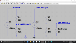
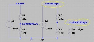
So 1k + the 2k2 gives a total of 3200 ohms from the opamp input to ground.
The opamp bias current is fixed (it doesn't depend on the resistance) and so we have a DC voltage across that resistance that depends solely on the resistance value itself.
So if the bias current for your 5532 were say 200 nano amps then the voltage at the opamp input would be 200E-9 multiplied by 3200 which is 0.640 millivolts or 640 microvolts.
That is the voltage at the opamp itself. Because the 2k2 and 1k are in series that voltage is split between the two resistors and you would actually see 200 microvolts across the cartridge and 440 microvolts across the 2k2.
Add them up and you get the 640 microvolt offset.
But ironically much more current noise so is noisier in a MM preamp. Doh!Fwiw, the LM4562 which is the 5532's successor has a much lower bias current.
(This is a consequence of bias-current cancellation which doesn't cancel noise unless the circuit is symmetric, which a phono preamp circuit isn't usually (unless you use an instrumentation-amp style balanced configuration)).
As far as i am concerned this circuit is defective; there should be no amount of dc current allowed to flow through a cartridge. Either use a fet input opamp or add a coupling cap.
But ironically much more current noise so is noisier in a MM preamp. Doh!
(This is a consequence of bias-current cancellation which doesn't cancel noise unless the circuit is symmetric, which a phono preamp circuit isn't usually (unless you use an instrumentation-amp style balanced configuration)).
Is it
I haven't looked into the finer points of using it for an MM preamp tbh. Are we talking big differences, or a quarter of a half of nothing If I were using this I would be inclined to fit a dummy resistance at the input and then whack the gain up full and just listen... and then try something else. If it was noticeably noisier with an alternative then you have to make a personal choice... and if not... then the choice is yours.
@Mooly,
did you mean "mV" at the circled figures sir?
As analog_sa says, they are correct and were generated (calculated) automatically by the simulator in that diagram... hence the many decimal places. The values in the earlier posts were quickly calculated long hand with a calculator and rounded for ease.
As far as i am concerned this circuit is defective; there should be no amount of dc current allowed to flow through a cartridge. Either use a fet input opamp or add a coupling cap.
Hmm... I kind of think that way as well. So most of the input bias current will flow in the cartridge (we can disregard the 47k for this). Would it introduce some non-linearity... I really don't know.
That makes sense. Its a very similar scenario to a tape head I suppose and you certainly wouldn't want any DC current flowing there. I've still got a tape head demagnetiser in a drawer.
So you've got me looking now. Ah, we have an old thread on the very subject:
Allowable DC Current for a Phono Cartridge
So you've got me looking now. Ah, we have an old thread on the very subject:Allowable DC Current for a Phono Cartridge
Its maybe a bit drastic to bin it when you have already built it
If you AC couple the input then the current falls to essentially zero (just leakage current of the coupling cap).
Why not try the LM4562 I mentioned. That would see the voltage across the 'open' input (no cartridge connected) fall to around 0.5 millivolts and the voltage across a 1k cartridge when connected would be around 9 microvolts which is negligible.
You could even experiment with devices such as the OP2134 which is a FET device and so has no measurable bias current flowing in or out of the input pins (well infinitesimally low as to be zero for all intents and purposes, much much lower than the leakage current of a coupling cap).
And I hear 'ya Mark
Code:
Low noise bipolar op amps such as the OPA27 and OPA37
provide very low voltage noise at the expense of a higher
current noise. However, OPA134 series op amps are unique
in providing very low voltage noise and very low current
noise. This provides optimum noise performance over a
wide range of sources, including reactive source impedances,
refer to the typical curve, “Voltage Noise vs Source
Resistance.” Above 2kW source resistance, the op amp
contributes little additional noise—the voltage and current
terms in the total noise equation become insignificant and
the source resistance term dominates. Below 2kW, op amp
voltage noise dominates over the resistor noise, but compares
favorably with other audio op amps such as OP176.As far as i am concerned this circuit is defective; there should be no amount of dc current allowed to flow through a cartridge. Either use a fet input opamp or add a coupling cap.
Its actually fine in practice, unless the circuit is defective and puts really high current spikes at switch on/off through the cartridge, a few 100nA is not a problem, its an incredibly small current for any electromagnetic component.
Even with a blocking cap you can still put large current spikes into a cartridge with
transients, although its a good level of protection from gross problems like opamp failing shorted between inputs and a rail.
- Status
- This old topic is closed. If you want to reopen this topic, contact a moderator using the "Report Post" button.
- Home
- Source & Line
- Analogue Source
- Voltage presence in phono preamp inputs? Is it right?