I’m starting this thread primarily as a place to exchange ideas for repairs, modifications, and photoelectric servo control systems to help keep the extant population of Rabco SL8E (and SL8) linear tonearms alive and working better than new. Ideas here could also be useful for other diy servo-linear arm projects, and conceivably spin off into new threads. First, a few requests for this thread that I hope everyone will respect and abide by:
This thread is intended for those who own, have built, like to tinker with, are addicted to, or otherwise admire electric/electronic servo-controlled linear tracking tonearms. Rabco SL8E owners move to the front of the line.
and:
PLEASE, no ‘servos are always in error’ arguments, no debates over servo linears vs passive linears, servo linears vs air linears, servo linears vs conventional pivoted tonearms, etc. Those skirmishes and battles have been fought out elsewhere on the internet, and invariably degrade into nuclear exchanges that trash the original thread. If you are anti-servo that’s fine, but you already have plenty of other forums to post your views and comments, and you’ve probably already done so.
To launch this thread, I’m posting my most recent work - a minimally invasive diy photoelectric retrofit to replace the troublesome catwhisker contacts on the Rabco SL8E. By ‘minimally invasive’ I mean that it requires no drilling or cutting of the carriage or original structure and is totally reversible (although I can’t imagine why you ever would want to undo this modification). The modification requires detaching the carriage and battery/drive motor housing from the track but does not require disassembling the horizontal/vertical arm pivot bearing assembly or the lift switch assembly. I put together a shared public shopping cart on Digi-Key (no financial interest) that includes all the electronic parts for the project. There is one part that you will have to diy that requires cutting, drilling, tapping and that is to fabricate a mounting block for the two photoelectric sensors. If you want to do a more extensive tear-down and include modifications like re-wire the cartridge leads/interconnects, replace the bead chain with a timing belt, etc., that is up to you and whatever you think will yield the audible improvements that you are looking for. This modification is only for the servo control. It will require advanced soldering skills and dexterity with a normal temperature-controlled soldering station.
My journey into modifying SL8E’s began in 1973, when a friend of mine handed me a SL8E and said “here, see what you can do with this”. He gave me full artistic license, and the goal was to optimize the design for the original mega-high-compliance ADC XLM cartridge. At that time, I had access to the machine shop at my engineering college, and I had access to a pretty good imagination as well. I replaced the entire OEM arm assembly with a low mass viscous damped unipivot and this eventually turned into a construction project article that was published in the 3/76 issue of The Audio Amateur magazine. I built two more SL8E’s with the unipivot mod, one for another friend and the other for myself. Since minimizing effective mass was a primary objective of the original mod, I deleted the convenient OEM vernier adjustment mechanism for setting 90-degree tracking angle and replaced it with a lightweight semi-fixed wand. The original mod retained the OEM catwhisker servo control. More on that later.
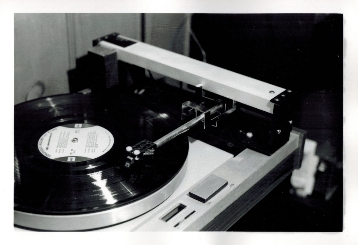
The original TAA 3/76 mod
That arm has remained my mainstay ever since and has provided me with unparalleled performance. (I’m not sure if that’s a pun or an oxymoron). The unipivot mod initially had a Rube Goldberg-ish cueing system as shown in the TAA article, but it worked reasonably well. By far, the biggest reliability problem turned out to be the progressively worsening erratic behavior of the catwhisker contact system that controlled the carriage drive motor. The classic failure mode was airborne contamination, which resulted in the cue motor lifting in the middle of the record. I went through years of routine maintenance cleaning of the catwhisker contacts. This helped for a while, but eventually the situation became unworkable. I designed a non-contact photoelectric servo control system out of necessity. While working on that I devised a much-improved cueing mechanism as well, which reduced the ridiculously high cueing height to just above the record surface and made the cue height vernier adjustable. The new photoelectric servo control circuit and cueing system has since worked flawlessly.
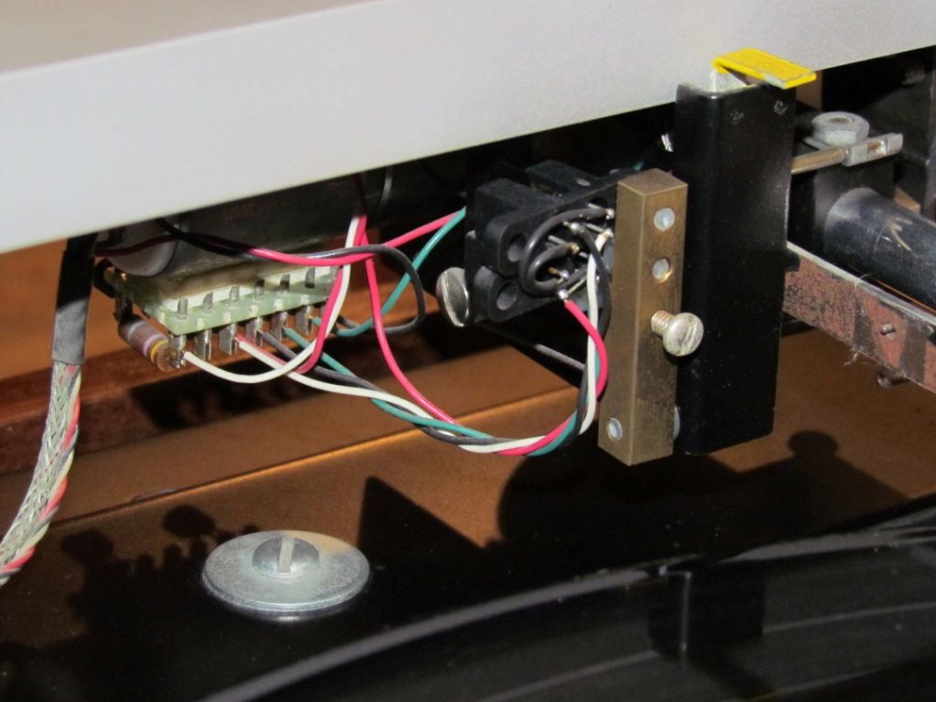
The original photoelectric upgrade, with electronic parts mounted outboard.
I initially thought the photoelectric circuit should duplicate the on/off action of the OEM catwhisker contacts. I contemplated employing a Schmitt trigger, but was up against the limited real estate available within the carriage for all the added circuitry. I though I could get away with achieving sharp on/off switch action by just using a simple circuit with high gain transistors, but I ended up being wrong about that. The carriage motor ran quickly at the lead-in groove, then settled down and ran slowly during the program material. Instead of start/stop motion like the OEM servo control, the carriage motor kept running continuously, and adjusted its speed in step with the varying groove pitch. Eureka! By serendipity, I ended up with continuous variable speed carriage control instead of mimicking the OEM on/off action. The continuous variable speed action has proven to have several advantages. First, it eliminated jackrabbit start, overshoot, and stop motion (“crabbing” as anti-servo crowd calls it). Second, and far more important in my estimation, the continuous slower speed operation of the carriage drive motor dramatically reduces physical motor noise.
I eventually tracked down the source of the beneficial ‘soft’ control action. It is the orientation of the aperture window in the photosensors and the fact that the aperture of the light-sensitive part of the phototransistor has a finite area. The sensor window is a rectangular slot. The manufacturer intended that the edge of the customer’s interrupting flag line up with the long edge of the sensor window, to minimize the transition time of the on/off state switching. Because of physical constraints I oriented the sensors at 90 degrees, such that the interrupting flag crossed the sensor window the ‘long’ way. Arm motion interrupts the optical beam gradually, much like the slow action of a solar eclipse, and provides the variable gain in the feedback loop which makes the carriage drive motor run smoothly in a continuous variable speed mode.
I’ve had several requests to share my servo control circuit and I have posted it on the Rabco SL8E Club thread over at LencoHeaven. The catch is, that the original circuit was developed for my unipivot configuration which had the photosenors mounted externally under the carriage and a semi-fixed wand on the arm pivot that un-interrupted the beam to advance the servo. The only practical way to design the photosensors to be inside the carriage requires a mounting arrangement that interrupts the light beam to activate the servo. This mounting arrangement is better suited as a retrofit mod because it retains the functionality of the OEM vernier adjustment mechanism for setting zero tracking error. I own two more OEM SL8E’s and decided to reconfigure and adapt my original photoelectric control circuit into a version that is optimized for installation on a stock SL8E. I retrofitted one of my extra SL8E’s with a redesigned photoelectric servo-control and I’m presenting those modification steps in this thread. I debated on whether to put most of the components on an externally mounted board as in my original mod, or to mount all the parts on/in the carriage for a clean, original look. Consider that a big advantage of the former is that an externally mounted components board makes it easy to tweak parts values in order to optimize performance. I felt confident that my circuit design should work because of the time I spent breadboarding and testing it so I opted for the latter. Both approaches have merit and you should choose a path based on your diy preferences.
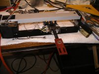
OK, so what evidence can I show to demonstrate that this is more than just another mod that was done for the sake of satisfying some expectation bias? To test compare the performance of the mod’ed and the stock versions of the arm, I fabricated and attached a diagnostics cable to the photoelectric retrofitted SL8E and another to the OEM stock SL8E. I monitored the servo ‘command’ signal, the right channel audio, and the actual carriage drive motor voltage while playing a typical music LP and displayed the three traces on a storage oscilloscope set to operate in auto-erase mode. The effect is very similar to a heart rate monitor display that you see on one of those medical TV soap operas.
Here is the scope trace mp4 for the stock OEM SL8E with cat whisker contact servo control:
YouTube
The upper trace is the contact closure command signal from the cat whisker to the carriage drive servo. The middle trace is the audio, straight from the cartridge with no RIAA EQ. The bottom trace is actual carriage drive motor voltage. The cat whisker contact does not provide a clean control signal, particularly on the tail end release. The motor voltage exhibits a repetitive pattern of jackrabbit start to full speed, then coast to a stop, then sit and wait until the next burst. (Note: the polarity of the trace is inverted due to the Positive Ground power supply, sorry). Clearly, this drive is ‘crabbing’ its way across the record. In fairness, I did take this SL8E apart, cleaned the cat whisker and contact post wires, installed a new foam gripper pad, cleaned, lubed, and adjusted the complete operating assembly to what I believe is factory spec. How much angular error is introduced by the crabbing? I suppose it could be analyzed and calculated, with a probable result that the angular error is less than that of a 9” pivoted arm, but let’s let that sleeping dog lie.
Here is the scope trace mp4 for the modified SL8E with photoelectric servo control:
YouTube
The upper trace is the command signal from the photoelectric sensor to the carriage drive servo. The middle trace is the audio, straight from the cartridge with no RIAA EQ. The bottom trace is actual carriage drive motor voltage. My initial reaction (and maybe yours) upon seeing these traces was “jeez, after all that work, this looks like crap”. After stewing for a while, I started to pick this apart a bit. Neither the upper trace command signal from the photoelectric sensor nor the lower trace of the actual carriage drive motor voltage exhibit any of the “full-on/off” jackrabbit start/stop behavior of the OEM stock cat whisker servo control – that’s been eliminated. The motor is now running continuously. To explain the voltage vacillation, look at the timing. The vacillation period is 1.8 seconds or 0.55Hz. The servo is unidirectionally attempting to follow the record eccentricity! I found that the magnitude of the vacillation corresponded to the magnitude of the eccentricity of the record being played. Well, that’s settled – all playback systems are compromised by eccentric records, so let’s move on.
It occurred to me that, if I had a record centering servo system on the spindle, and if I fed it a properly filtered and phased copy of this arm’s error correction signal, the record should perfectly center itself automatically while playing within a few revolutions. Hmmm.
Next post – the mod.
Ray K
This thread is intended for those who own, have built, like to tinker with, are addicted to, or otherwise admire electric/electronic servo-controlled linear tracking tonearms. Rabco SL8E owners move to the front of the line.
and:
PLEASE, no ‘servos are always in error’ arguments, no debates over servo linears vs passive linears, servo linears vs air linears, servo linears vs conventional pivoted tonearms, etc. Those skirmishes and battles have been fought out elsewhere on the internet, and invariably degrade into nuclear exchanges that trash the original thread. If you are anti-servo that’s fine, but you already have plenty of other forums to post your views and comments, and you’ve probably already done so.
To launch this thread, I’m posting my most recent work - a minimally invasive diy photoelectric retrofit to replace the troublesome catwhisker contacts on the Rabco SL8E. By ‘minimally invasive’ I mean that it requires no drilling or cutting of the carriage or original structure and is totally reversible (although I can’t imagine why you ever would want to undo this modification). The modification requires detaching the carriage and battery/drive motor housing from the track but does not require disassembling the horizontal/vertical arm pivot bearing assembly or the lift switch assembly. I put together a shared public shopping cart on Digi-Key (no financial interest) that includes all the electronic parts for the project. There is one part that you will have to diy that requires cutting, drilling, tapping and that is to fabricate a mounting block for the two photoelectric sensors. If you want to do a more extensive tear-down and include modifications like re-wire the cartridge leads/interconnects, replace the bead chain with a timing belt, etc., that is up to you and whatever you think will yield the audible improvements that you are looking for. This modification is only for the servo control. It will require advanced soldering skills and dexterity with a normal temperature-controlled soldering station.
My journey into modifying SL8E’s began in 1973, when a friend of mine handed me a SL8E and said “here, see what you can do with this”. He gave me full artistic license, and the goal was to optimize the design for the original mega-high-compliance ADC XLM cartridge. At that time, I had access to the machine shop at my engineering college, and I had access to a pretty good imagination as well. I replaced the entire OEM arm assembly with a low mass viscous damped unipivot and this eventually turned into a construction project article that was published in the 3/76 issue of The Audio Amateur magazine. I built two more SL8E’s with the unipivot mod, one for another friend and the other for myself. Since minimizing effective mass was a primary objective of the original mod, I deleted the convenient OEM vernier adjustment mechanism for setting 90-degree tracking angle and replaced it with a lightweight semi-fixed wand. The original mod retained the OEM catwhisker servo control. More on that later.
The original TAA 3/76 mod
That arm has remained my mainstay ever since and has provided me with unparalleled performance. (I’m not sure if that’s a pun or an oxymoron). The unipivot mod initially had a Rube Goldberg-ish cueing system as shown in the TAA article, but it worked reasonably well. By far, the biggest reliability problem turned out to be the progressively worsening erratic behavior of the catwhisker contact system that controlled the carriage drive motor. The classic failure mode was airborne contamination, which resulted in the cue motor lifting in the middle of the record. I went through years of routine maintenance cleaning of the catwhisker contacts. This helped for a while, but eventually the situation became unworkable. I designed a non-contact photoelectric servo control system out of necessity. While working on that I devised a much-improved cueing mechanism as well, which reduced the ridiculously high cueing height to just above the record surface and made the cue height vernier adjustable. The new photoelectric servo control circuit and cueing system has since worked flawlessly.
The original photoelectric upgrade, with electronic parts mounted outboard.
I initially thought the photoelectric circuit should duplicate the on/off action of the OEM catwhisker contacts. I contemplated employing a Schmitt trigger, but was up against the limited real estate available within the carriage for all the added circuitry. I though I could get away with achieving sharp on/off switch action by just using a simple circuit with high gain transistors, but I ended up being wrong about that. The carriage motor ran quickly at the lead-in groove, then settled down and ran slowly during the program material. Instead of start/stop motion like the OEM servo control, the carriage motor kept running continuously, and adjusted its speed in step with the varying groove pitch. Eureka! By serendipity, I ended up with continuous variable speed carriage control instead of mimicking the OEM on/off action. The continuous variable speed action has proven to have several advantages. First, it eliminated jackrabbit start, overshoot, and stop motion (“crabbing” as anti-servo crowd calls it). Second, and far more important in my estimation, the continuous slower speed operation of the carriage drive motor dramatically reduces physical motor noise.
I eventually tracked down the source of the beneficial ‘soft’ control action. It is the orientation of the aperture window in the photosensors and the fact that the aperture of the light-sensitive part of the phototransistor has a finite area. The sensor window is a rectangular slot. The manufacturer intended that the edge of the customer’s interrupting flag line up with the long edge of the sensor window, to minimize the transition time of the on/off state switching. Because of physical constraints I oriented the sensors at 90 degrees, such that the interrupting flag crossed the sensor window the ‘long’ way. Arm motion interrupts the optical beam gradually, much like the slow action of a solar eclipse, and provides the variable gain in the feedback loop which makes the carriage drive motor run smoothly in a continuous variable speed mode.
I’ve had several requests to share my servo control circuit and I have posted it on the Rabco SL8E Club thread over at LencoHeaven. The catch is, that the original circuit was developed for my unipivot configuration which had the photosenors mounted externally under the carriage and a semi-fixed wand on the arm pivot that un-interrupted the beam to advance the servo. The only practical way to design the photosensors to be inside the carriage requires a mounting arrangement that interrupts the light beam to activate the servo. This mounting arrangement is better suited as a retrofit mod because it retains the functionality of the OEM vernier adjustment mechanism for setting zero tracking error. I own two more OEM SL8E’s and decided to reconfigure and adapt my original photoelectric control circuit into a version that is optimized for installation on a stock SL8E. I retrofitted one of my extra SL8E’s with a redesigned photoelectric servo-control and I’m presenting those modification steps in this thread. I debated on whether to put most of the components on an externally mounted board as in my original mod, or to mount all the parts on/in the carriage for a clean, original look. Consider that a big advantage of the former is that an externally mounted components board makes it easy to tweak parts values in order to optimize performance. I felt confident that my circuit design should work because of the time I spent breadboarding and testing it so I opted for the latter. Both approaches have merit and you should choose a path based on your diy preferences.
OK, so what evidence can I show to demonstrate that this is more than just another mod that was done for the sake of satisfying some expectation bias? To test compare the performance of the mod’ed and the stock versions of the arm, I fabricated and attached a diagnostics cable to the photoelectric retrofitted SL8E and another to the OEM stock SL8E. I monitored the servo ‘command’ signal, the right channel audio, and the actual carriage drive motor voltage while playing a typical music LP and displayed the three traces on a storage oscilloscope set to operate in auto-erase mode. The effect is very similar to a heart rate monitor display that you see on one of those medical TV soap operas.
Here is the scope trace mp4 for the stock OEM SL8E with cat whisker contact servo control:
YouTube
The upper trace is the contact closure command signal from the cat whisker to the carriage drive servo. The middle trace is the audio, straight from the cartridge with no RIAA EQ. The bottom trace is actual carriage drive motor voltage. The cat whisker contact does not provide a clean control signal, particularly on the tail end release. The motor voltage exhibits a repetitive pattern of jackrabbit start to full speed, then coast to a stop, then sit and wait until the next burst. (Note: the polarity of the trace is inverted due to the Positive Ground power supply, sorry). Clearly, this drive is ‘crabbing’ its way across the record. In fairness, I did take this SL8E apart, cleaned the cat whisker and contact post wires, installed a new foam gripper pad, cleaned, lubed, and adjusted the complete operating assembly to what I believe is factory spec. How much angular error is introduced by the crabbing? I suppose it could be analyzed and calculated, with a probable result that the angular error is less than that of a 9” pivoted arm, but let’s let that sleeping dog lie.
Here is the scope trace mp4 for the modified SL8E with photoelectric servo control:
YouTube
The upper trace is the command signal from the photoelectric sensor to the carriage drive servo. The middle trace is the audio, straight from the cartridge with no RIAA EQ. The bottom trace is actual carriage drive motor voltage. My initial reaction (and maybe yours) upon seeing these traces was “jeez, after all that work, this looks like crap”. After stewing for a while, I started to pick this apart a bit. Neither the upper trace command signal from the photoelectric sensor nor the lower trace of the actual carriage drive motor voltage exhibit any of the “full-on/off” jackrabbit start/stop behavior of the OEM stock cat whisker servo control – that’s been eliminated. The motor is now running continuously. To explain the voltage vacillation, look at the timing. The vacillation period is 1.8 seconds or 0.55Hz. The servo is unidirectionally attempting to follow the record eccentricity! I found that the magnitude of the vacillation corresponded to the magnitude of the eccentricity of the record being played. Well, that’s settled – all playback systems are compromised by eccentric records, so let’s move on.
It occurred to me that, if I had a record centering servo system on the spindle, and if I fed it a properly filtered and phased copy of this arm’s error correction signal, the record should perfectly center itself automatically while playing within a few revolutions. Hmmm.
Next post – the mod.
Ray K
Attachments
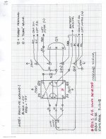
Schematic, Wiring Diagrams, Support Dimensions, Construction Sequence, Parts List
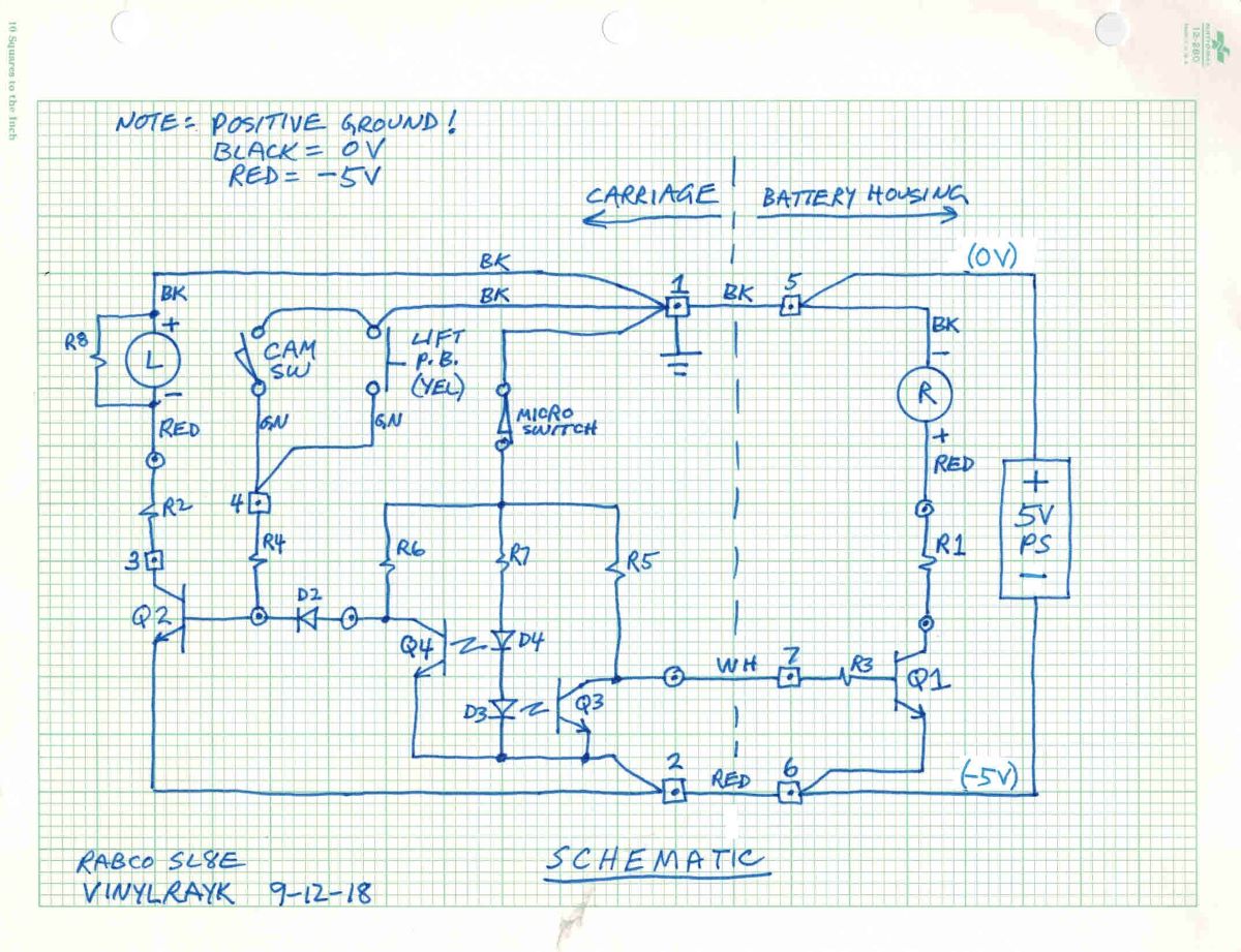
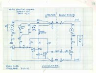
Photo A - Schematic Diagram (replace microswitch with jumper)
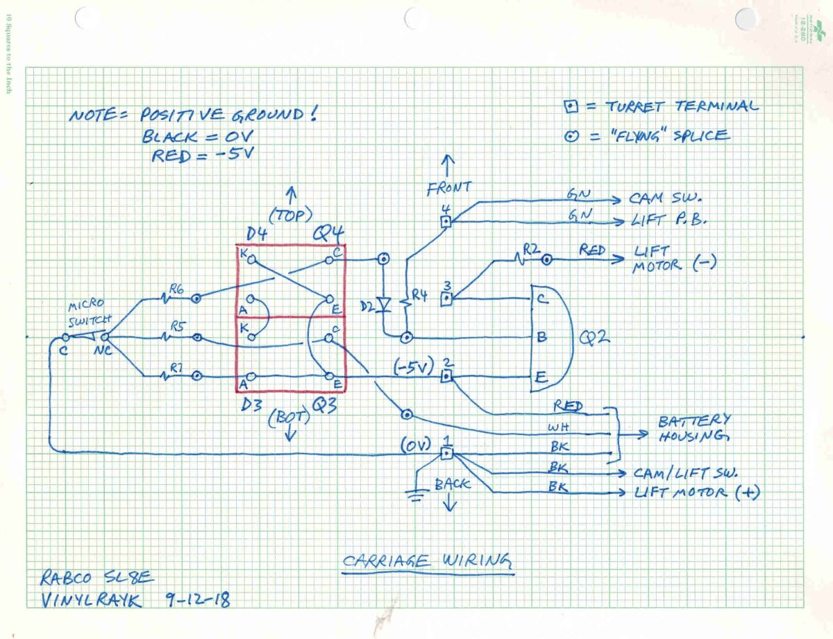
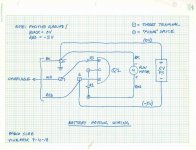
Photo B - Photosensor assembly and turret wiring diagram (replace microswitch with jumper)
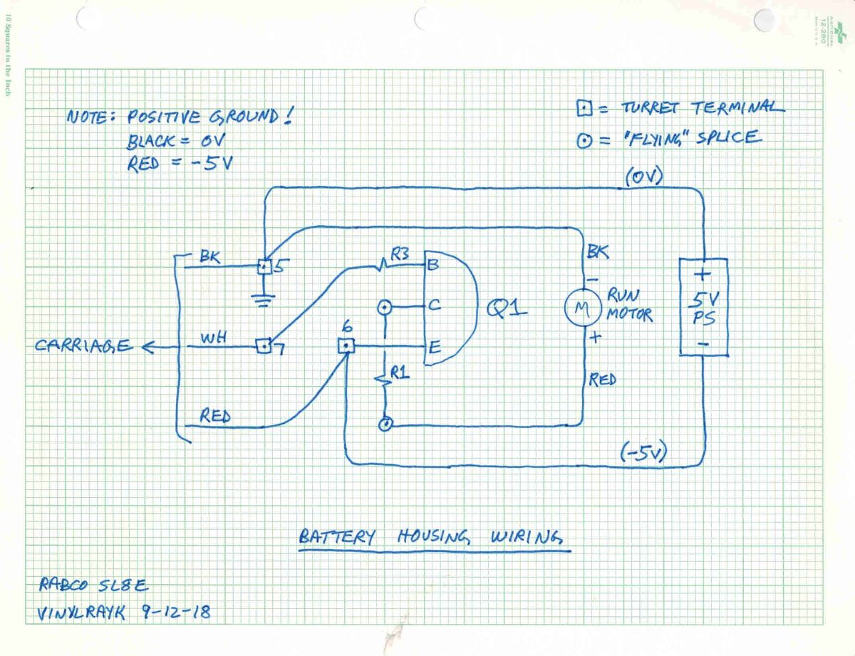
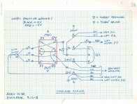
Photo C - Battery housing wiring diagram
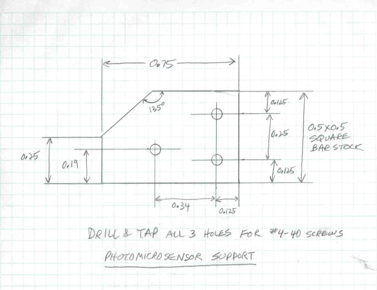
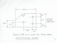
Photo D – Photosensor mounting support block dimensions.
Photosensor support can be metal or plastic and is made from 0.5 x 0.5 inch bar stock. It is fastened to the carriage chassis via the hole that was previously used to attach the OEM catwhisker assembly. The proper depth of the photosensors is achieved by adding spacers under the photosensor mounting tabs.
The construction sequence is 5 pages of detailed notes (almost like a Heathkit assembly manual) and, rather than put all that into a lengthy post, I'm including it as a PDF. I will revise and update the construction sequence as needed and based on 'user' comments:
See attached file.
Parts List:
See attached file.
A kit of the electronic parts is available in this 'Shared Shopping Cart':
Digi-Key - Fast Add
More photos coming.
Ray K
Photo A - Schematic Diagram (replace microswitch with jumper)
Photo B - Photosensor assembly and turret wiring diagram (replace microswitch with jumper)
Photo C - Battery housing wiring diagram
Photo D – Photosensor mounting support block dimensions.
Photosensor support can be metal or plastic and is made from 0.5 x 0.5 inch bar stock. It is fastened to the carriage chassis via the hole that was previously used to attach the OEM catwhisker assembly. The proper depth of the photosensors is achieved by adding spacers under the photosensor mounting tabs.
The construction sequence is 5 pages of detailed notes (almost like a Heathkit assembly manual) and, rather than put all that into a lengthy post, I'm including it as a PDF. I will revise and update the construction sequence as needed and based on 'user' comments:
See attached file.
Parts List:
See attached file.
A kit of the electronic parts is available in this 'Shared Shopping Cart':
Digi-Key - Fast Add
More photos coming.
Ray K
Attachments
Last edited:
Photos 01-06
Here are the modification photos. I wrote up the modification steps in a recommended sequence of construction with reference photos – kind of like a Heathkit assembly manual. The sequence of construction is 5 pages and was posted in a separate PDF file, which I will periodically update and repost with corrections and changes based on user suggestions.
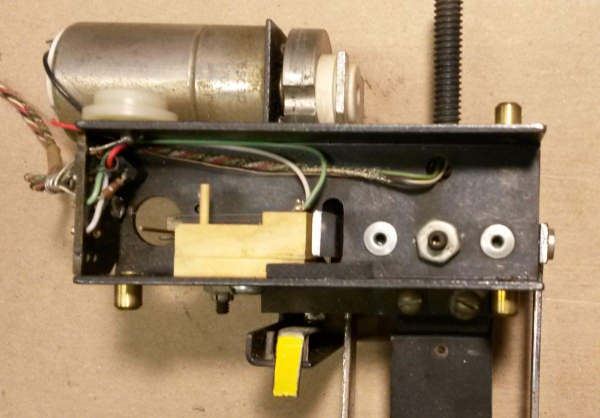
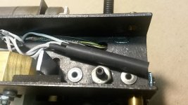
Photo 01 - OEM Stock Carriage Layout
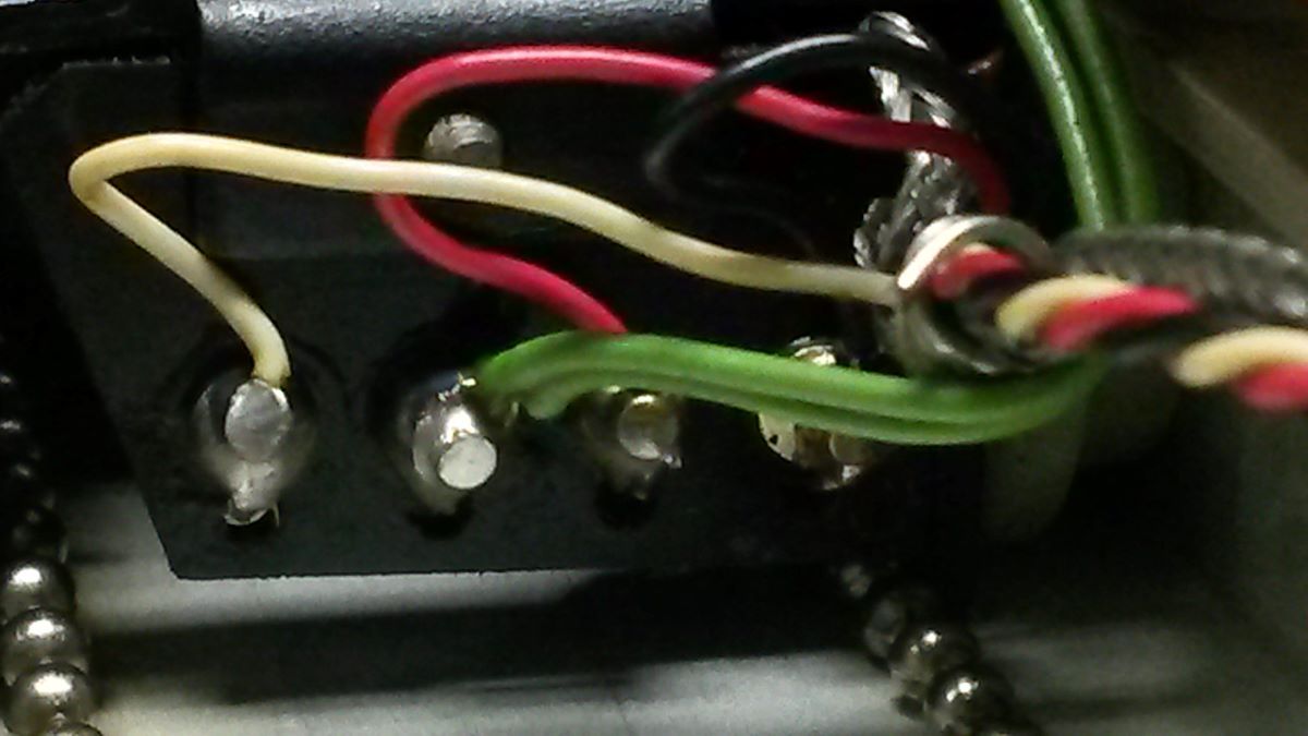
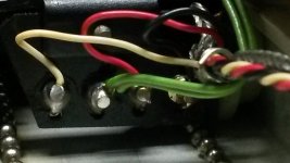
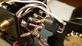
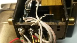
Photo 02 - Turret Wiring. Read the construction sequence notes carefully about protecting the "wrapped" cable/wires from heat damage while soldering!
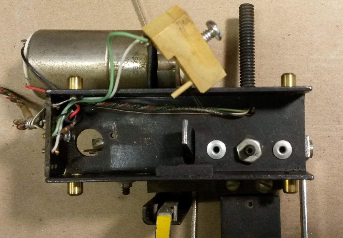
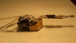
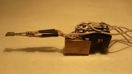
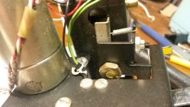
Photo 03 – Unsolder and remove the CatWhisker assembly. Do NOT remove the vertical contact post or disassemble the 90 degree setscrew adjustment mechanism.

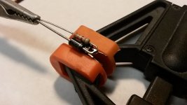
Photo 04 – Completely unsolder and remove the transistor and resistor. Don't try to salvage them, they will be replaced with new. Wrap a piece of aluminum duct tape on the vertical contact post to form a new beam interrupter flag.
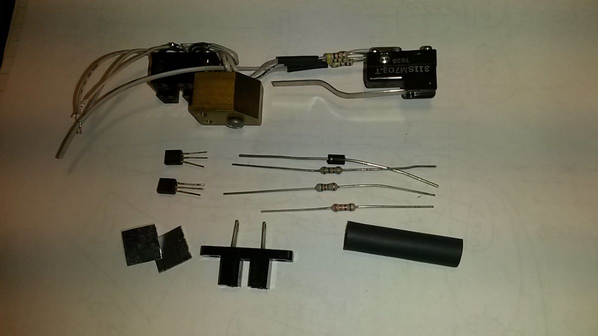
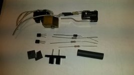
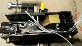
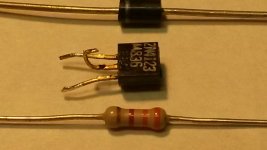
Photo 05 - New Parts (Note: the 311SM703-T microswitch has been deleted from the project)

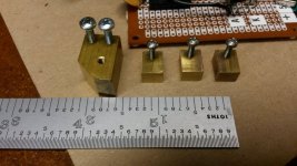
Photo 06 - Photosensor mounting block is on the left. (The other parts have been deleted.)
More photos coming.
Ray K
Here are the modification photos. I wrote up the modification steps in a recommended sequence of construction with reference photos – kind of like a Heathkit assembly manual. The sequence of construction is 5 pages and was posted in a separate PDF file, which I will periodically update and repost with corrections and changes based on user suggestions.
Photo 01 - OEM Stock Carriage Layout
Photo 02 - Turret Wiring. Read the construction sequence notes carefully about protecting the "wrapped" cable/wires from heat damage while soldering!
Photo 03 – Unsolder and remove the CatWhisker assembly. Do NOT remove the vertical contact post or disassemble the 90 degree setscrew adjustment mechanism.
Photo 04 – Completely unsolder and remove the transistor and resistor. Don't try to salvage them, they will be replaced with new. Wrap a piece of aluminum duct tape on the vertical contact post to form a new beam interrupter flag.
Photo 05 - New Parts (Note: the 311SM703-T microswitch has been deleted from the project)
Photo 06 - Photosensor mounting block is on the left. (The other parts have been deleted.)
More photos coming.
Ray K
Attachments


Photos 07-13
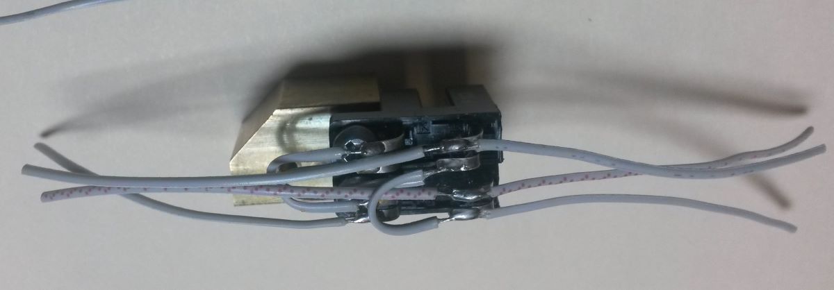
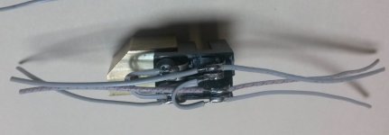
Photo 07 - Photosensor and mounting block subassembly. This needs to be pre-assembled, the solder connections will become inaccessible later. Note: It is necessary to cut off one of the mounting tabs on each of the two photosensors. Cut off the tabs on the side with the ‘C’ and ‘E’ leads.

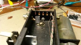
Photo 08 - Parts test-fitted in carriage. (The 311SM703-T microswitch has been deleted, ignore that.) Note the spacers under the photosensor mounting tabs. The proper dimensions to position the photosensor aperture such that the beam interrupting flag starts to block the beam when the OEM vertical contact post is centered in the round hole in the bottom of the carriage.
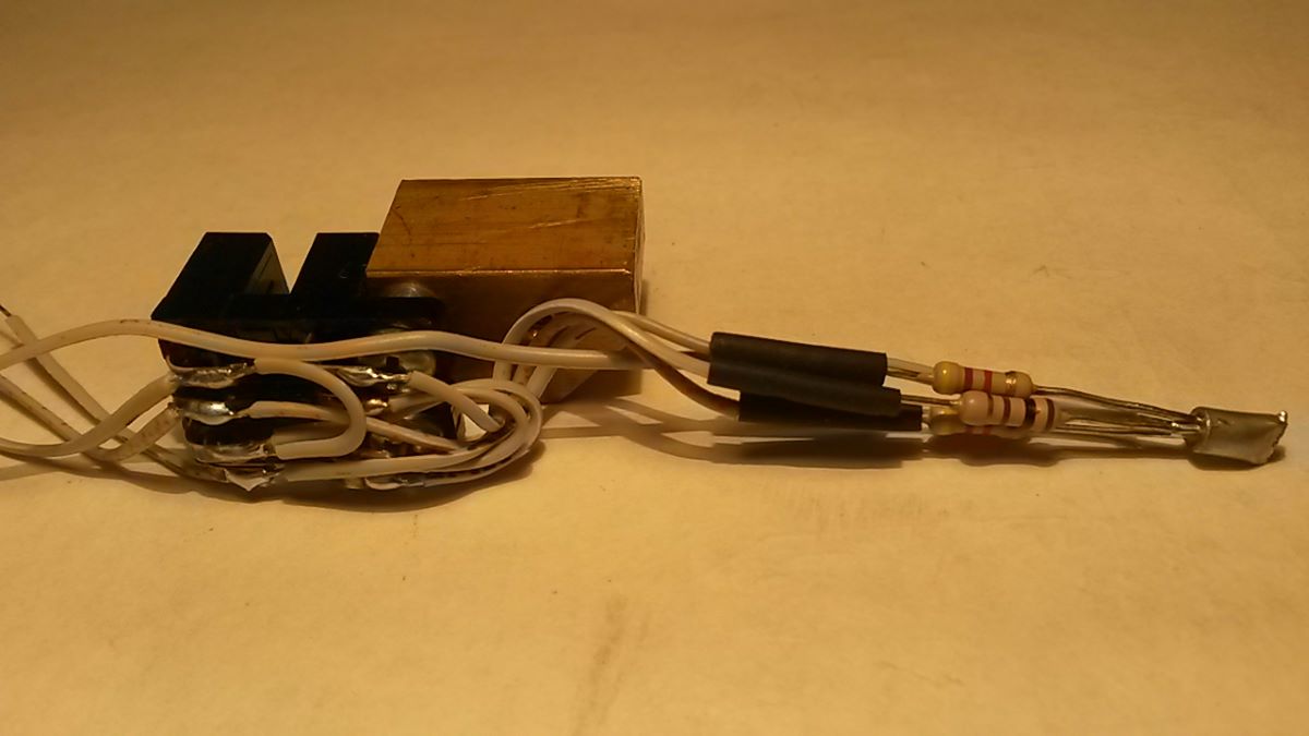
Photo 09 - Photosensor subassembly – back view.

Photo 10 - Photosensor subassembly – bottom view.

Photo 11 - Photosensor subassembly – top view.
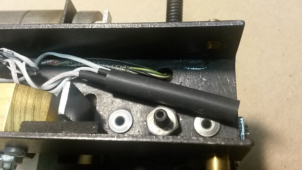
Photo 12 - R5/R6/R7 bundled together and in position. Do not crowd the cartridge signal wires and keep clear of the chrome chain grip lever.

Photo 13 - Tape the R5/R6/R7 bundle down to the carriage bottom
More photos coming.
Ray K
Photo 07 - Photosensor and mounting block subassembly. This needs to be pre-assembled, the solder connections will become inaccessible later. Note: It is necessary to cut off one of the mounting tabs on each of the two photosensors. Cut off the tabs on the side with the ‘C’ and ‘E’ leads.
Photo 08 - Parts test-fitted in carriage. (The 311SM703-T microswitch has been deleted, ignore that.) Note the spacers under the photosensor mounting tabs. The proper dimensions to position the photosensor aperture such that the beam interrupting flag starts to block the beam when the OEM vertical contact post is centered in the round hole in the bottom of the carriage.
Photo 09 - Photosensor subassembly – back view.
Photo 10 - Photosensor subassembly – bottom view.
Photo 11 - Photosensor subassembly – top view.
Photo 12 - R5/R6/R7 bundled together and in position. Do not crowd the cartridge signal wires and keep clear of the chrome chain grip lever.
Photo 13 - Tape the R5/R6/R7 bundle down to the carriage bottom
More photos coming.
Ray K
Attachments
-
 13_R5,6,7 Bundle Taped Down.jpg294.4 KB · Views: 1,146
 -
 12_R5,6,7 Bundle Positioned.jpg289.5 KB · Views: 1,148
 -
 11_Opto Sub-assembly Top.jpg215.9 KB · Views: 1,245
 -
 10_Opto Sub-assembly Bot.jpg214.6 KB · Views: 1,219
 -
 09_Opto Sub-assembly Back.jpg218.2 KB · Views: 1,254
 -
 08_Parts Test-Fitted.jpg87 KB · Views: 1,241
 -
 07_Opto Module Wiring.jpg711.1 KB · Views: 1,177
Photos 14-21

Photo 14 - Q2 Base ‘Hook’. Pre-shape the leads for the 'flying connections' and the turret connections.
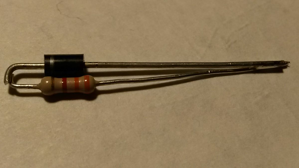
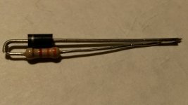
Photo 15 - D2/R2 Pre-soldered Tail. This will hold the two together while soldering the other end to the Q2 Base 'Hook'.

Photo 16 - D2/R4 Soldered to Q2 Base 'Hook'. Keep them tight together.

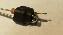
Photo 17 - Q2/D2/R4 Sub-assembly. Hold it all together with heat shrink.
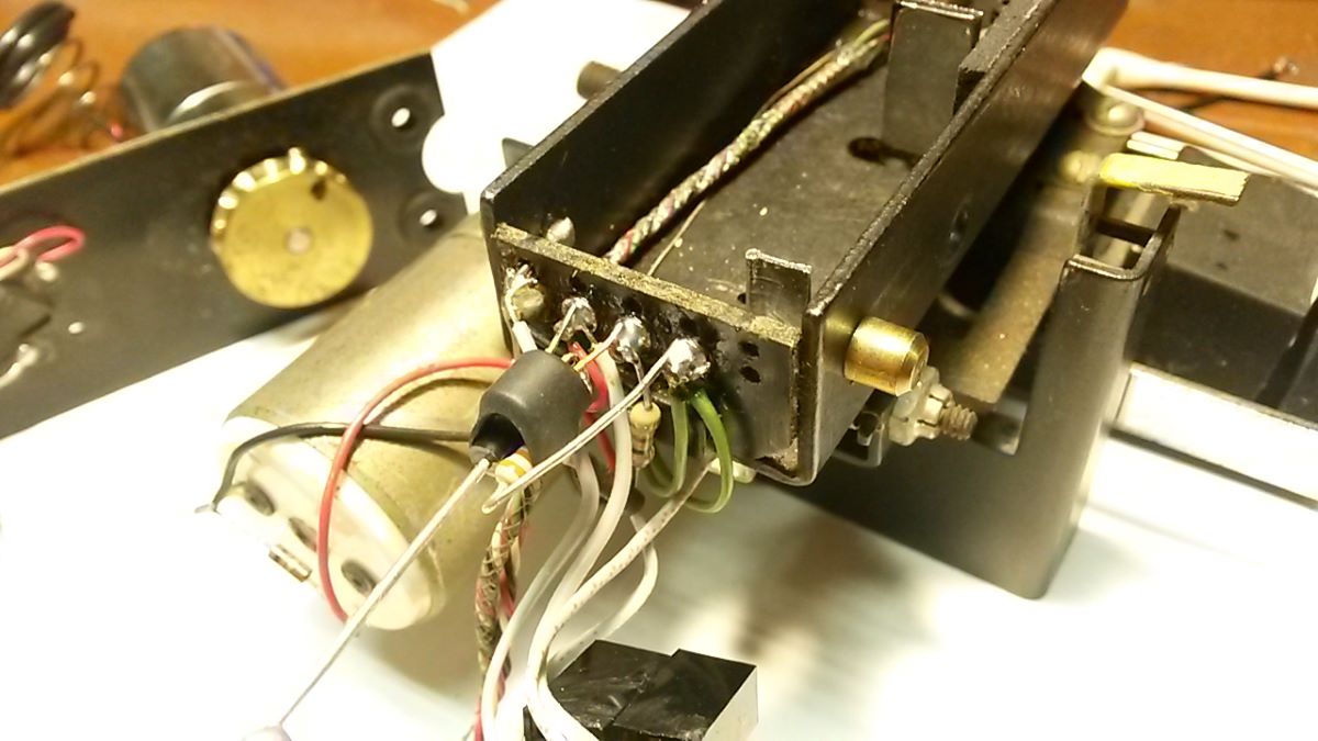
Photo 18 - Turret Connections - View 1
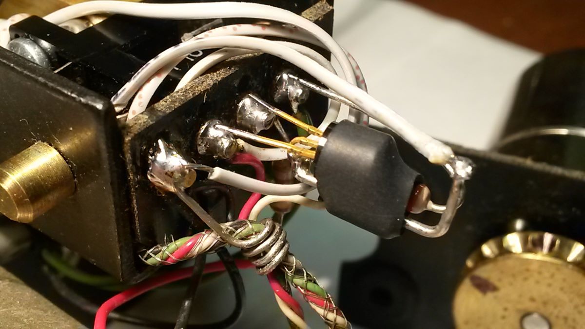
Photo 19 - Turret Connections – View 2
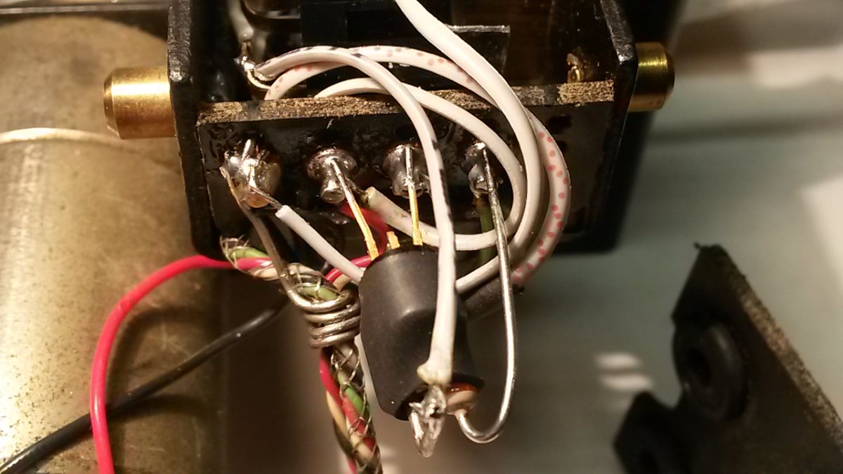
Photo 20 - Turret Connections – View 3
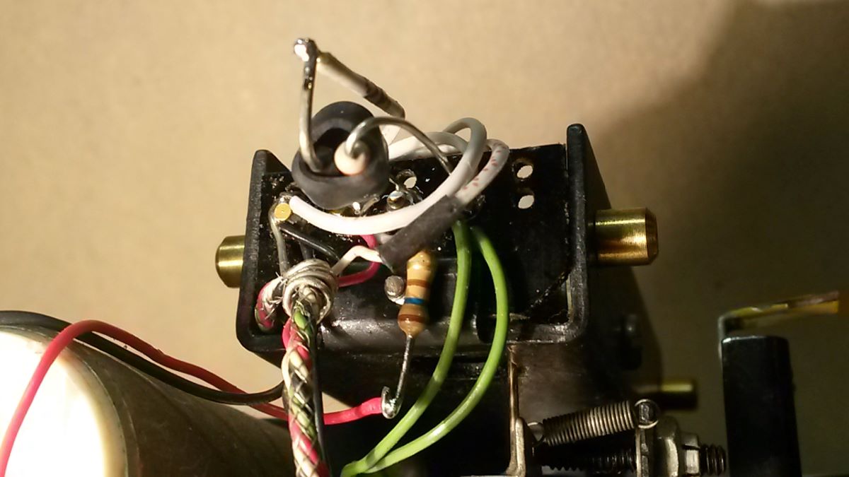
Photo 21 - Turret Connections – View 4
More photos coming.
Ray K
Photo 14 - Q2 Base ‘Hook’. Pre-shape the leads for the 'flying connections' and the turret connections.
Photo 15 - D2/R2 Pre-soldered Tail. This will hold the two together while soldering the other end to the Q2 Base 'Hook'.
Photo 16 - D2/R4 Soldered to Q2 Base 'Hook'. Keep them tight together.
Photo 17 - Q2/D2/R4 Sub-assembly. Hold it all together with heat shrink.
Photo 18 - Turret Connections - View 1
Photo 19 - Turret Connections – View 2
Photo 20 - Turret Connections – View 3
Photo 21 - Turret Connections – View 4
More photos coming.
Ray K
Attachments
-
 21_Turret Conx4.jpg271.4 KB · Views: 1,124
 -
 20_Turret Conx3.jpg313.8 KB · Views: 1,128
 -
 19_Turret Conx2.jpg329.2 KB · Views: 1,140
 -
 18_Turret Conx1.jpg303.3 KB · Views: 1,178
 -
 17_Q2-D2-R4 Sub-assembly.jpg208.5 KB · Views: 1,213
 -
 16_D2-R4 Pre-soldered to Q2 Base.jpg249.2 KB · Views: 1,145
 -
 15_D2-R4 Pre-soldered Tail.jpg225.3 KB · Views: 1,211
 -
 14_Q2 Base 'Hook'.jpg226.2 KB · Views: 1,187
Photos 22-26
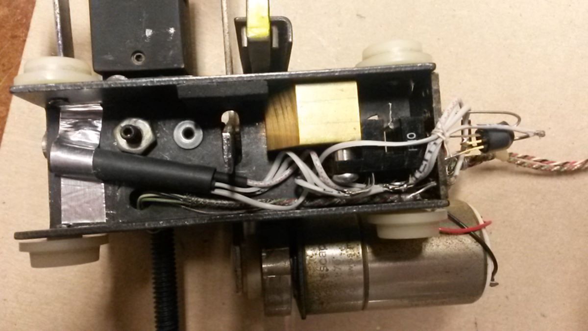
Photo 22- Completed Carriage. This is what it looked like before final re-assembly.
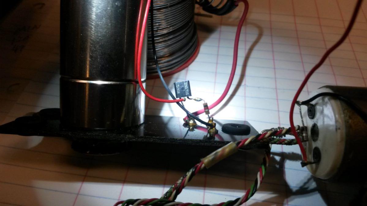
Photo 23 - OEM Carriage Drive Transistor Q1. Disconnect the red carriage drive motor lead from the collector lead.

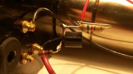
Photo 24 - New Resistor R1 Added to Q1 collector in series with the carriage drive motor.

Photo 25 - Secure top wires to center of turret insulator with thread. It is important that everything gets tied to the center and out of the way of the chain paths. In operation, the drive chain actually rests on the top edge of the turret terminal insulator 'board'. Note the wear marks above the outboard turrets where the chain 'rides'. Let it do that - if the chain is too taut it will stress the carriage drive reduction gear bearing or even 'twang' at some resonance frequency. All new parts and wiring have to be centered and not foul the chain.

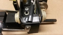
Photo 26 – Secure underside green wires out of the way with thread to not interfere with free movement of the arm's tangency adjustment mechanism.
That's it for now.
Ray K
Photo 22- Completed Carriage. This is what it looked like before final re-assembly.
Photo 23 - OEM Carriage Drive Transistor Q1. Disconnect the red carriage drive motor lead from the collector lead.
Photo 24 - New Resistor R1 Added to Q1 collector in series with the carriage drive motor.
Photo 25 - Secure top wires to center of turret insulator with thread. It is important that everything gets tied to the center and out of the way of the chain paths. In operation, the drive chain actually rests on the top edge of the turret terminal insulator 'board'. Note the wear marks above the outboard turrets where the chain 'rides'. Let it do that - if the chain is too taut it will stress the carriage drive reduction gear bearing or even 'twang' at some resonance frequency. All new parts and wiring have to be centered and not foul the chain.
Photo 26 – Secure underside green wires out of the way with thread to not interfere with free movement of the arm's tangency adjustment mechanism.
That's it for now.
Ray K
Attachments


A true step by step.
Thank you-
Only criticism I can make is bullets instead of check boxes?
Last kit I assembled was a Heathkit.
Your comments have been forwarded to the manual writing department.

Ray K
Ray thanks so much for this. Just fired it up for the first time this mourning and (I think) found a small error in the optical sensor schematic. You show a connection between the A and E terminals of the lower sensor that I think should not be there. Thanks again.
Richard
Richard
My bad
Richard,
I'm really sorry about that. You are correct, the connection between A and E does not match the schematic. I found a revised wiring diagram in my files. It looks like I uploaded an old one instead of the right one. I hope you followed the wiring in the photos and didn't pull out too much hair over this.
Ray K
Attachments
No problem Ray
I'm very pleased with the way it's working. I'm also following your lead with a uni-pivot and was able to incorporate the arm lift with (in) the fluid damping trough which I hope may eliminate the end of record "noise at lift" some have reported.
Rich
I'm very pleased with the way it's working. I'm also following your lead with a uni-pivot and was able to incorporate the arm lift with (in) the fluid damping trough which I hope may eliminate the end of record "noise at lift" some have reported.
Rich
Attachments
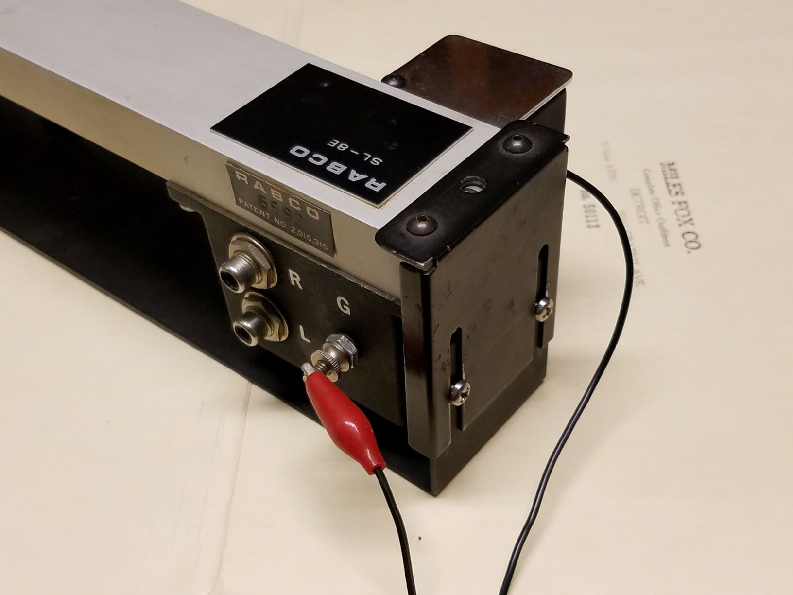
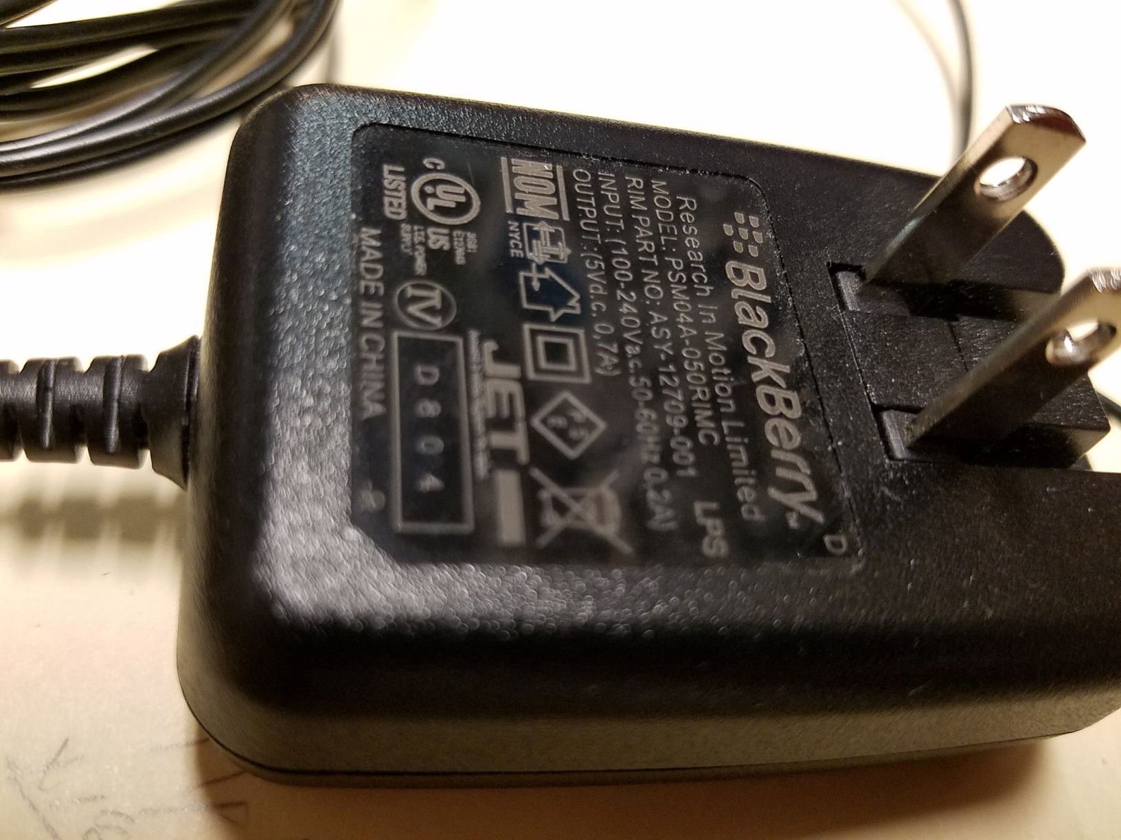
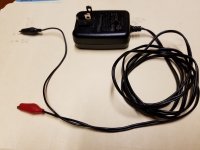
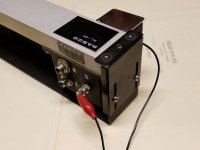
The circuit was designed to work from a 5VDC supply. I chose 5V to take advantage of the relative abundance of surplus/discarded cellphone and USB chargers. I didn’t want to deal with battery drain and inconsistent voltage. Cut the connector off the device end of the charger cord. Separate the end wires, strip, and attach color coded alligator clips. The positive lead alligator clip (red) goes to the grounding post on the drive housing. The negative lead alligator clip (black) goes to the coil spring contact in the bottom of the housing where the C cell used to go. Alternatively, you could diy a simple power supply around an inexpensive 7805 regulator IC. See Figure 17 in the attached datasheet.
Ray K

Ray K
Attachments
Excellent. Thanks for the explanation. If we are running 5v to the original power input where the C cell was then that means the lift/lower function will run faster. That's probably an added bonus. Might prevent the stylus from snagging the groove as it is raised. Is that the experience you have had with this mod?
Only concern might be if the arm lowering function is too fast now?
Only concern might be if the arm lowering function is too fast now?
R2 is sized to drop enough voltage to limit the lift motor speed close to OEM. The lift motor can be made to run faster but then you run into the problem of the motor overtravelling the "stop" notch of the cam and it will cycle endlessly. Some have machined a wider notch in the cam to compensate for this, but then you have to accurately guess how much wider the notch needs to be. If you guess wrong, it's hard to go back. And, if it lifts faster then it drops faster.
Similarly, R1 is sized to drop enough voltage to make the max carriage drive speed close to OEM. In actual operation, the carriage drive motor will run way slower and in continuously variable speed mode, which makes the tracking action smoother and the motor runs quietly.
Ray K
Similarly, R1 is sized to drop enough voltage to make the max carriage drive speed close to OEM. In actual operation, the carriage drive motor will run way slower and in continuously variable speed mode, which makes the tracking action smoother and the motor runs quietly.
Ray K
- Home
- Source & Line
- Analogue Source
- Rabco SL8E Photoelectric Servo Control Retrofit