Dear all,
Recently I have built a very simple RIAA preamplifier (for a moderate output moving coil cartridge) and line stage, in order to play LP records and CDs in our living room. Since my power amp (Van Medevoort PA222) has no volume or level controls at its input, I needed a preamp. The preamp was built using parts of the junkbox, and all PCBs were homemade and home-designed. Since I did not use anything special, I didn't expect much, but the sonic results were excellent. Thus, I will present my little project in a few posts to this forum, starting with the RIAA preamplifier.
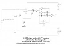
The RIAA preamp circuit that I used was published by John Linsley Hood, in the magazine Electronics World + Wireless World, June 1993 ("An Integrated Audio Amplifier"). John used two LM833 op-amps, which I replaced by two NE5532s (Philips) since I did not have LM833s in the junkbox. An "input impedance conversion stage" (linear gain block) is followed by a RIAA equalisation stage with shunt feedback. Although the use of shunt feedback rather than series feedback results in higher noise, the reproduction of transients by a shunt feedback system is superior. And I can report that the noise of this preamp is not objectionable, in fact, it is much lower than the surface noise of most LPs. All my capacitors were of decent quality and good accuracy. Styroflex and MKP types were used for the RIAA network, input and coupling caps, low ESR types for the electrolytics and multilayer ceramics for decoupling of the power supply lines. A kit for the RIAA preamp has been supplied by Hart Electronics ("K1500 Shunt Feedback RIAA Preamp"), but that company no longer exists.
Although I used ICs that can be purchased for 26 Eurocents (e.g. from Pollin in Germany), the preamp sounds great! This was also reported by David Hembrow, a UK citizen living in the Netherlands (see his homepage at hembrow.eu). Very minor details in recordings are revealed, and the placing of instruments on the soundstage is very accurate. The soundstage is both wide and deep. Improvements are perhaps possible (one could e.g. replace the first opamp by a "better" type such as the SSM2139), but right now, I'll leave everything as it is. I'm happy listening to my old records..... In case you wonder: I use an Audio Technica OC30 mc cartridge mounted in a Pioneer PLX-1000 direct drive turntable. And my speakers are exponential horns (Jericho horns with Fostex FE208 Sigma fullrange drive units).
To this post I attach: a. Circuit of the preamp; b. Bottom side of my home-designed PCB; c. Top side of the PCB (please note the presence of two wire links).
Best regards,
arensattic
Recently I have built a very simple RIAA preamplifier (for a moderate output moving coil cartridge) and line stage, in order to play LP records and CDs in our living room. Since my power amp (Van Medevoort PA222) has no volume or level controls at its input, I needed a preamp. The preamp was built using parts of the junkbox, and all PCBs were homemade and home-designed. Since I did not use anything special, I didn't expect much, but the sonic results were excellent. Thus, I will present my little project in a few posts to this forum, starting with the RIAA preamplifier.
The RIAA preamp circuit that I used was published by John Linsley Hood, in the magazine Electronics World + Wireless World, June 1993 ("An Integrated Audio Amplifier"). John used two LM833 op-amps, which I replaced by two NE5532s (Philips) since I did not have LM833s in the junkbox. An "input impedance conversion stage" (linear gain block) is followed by a RIAA equalisation stage with shunt feedback. Although the use of shunt feedback rather than series feedback results in higher noise, the reproduction of transients by a shunt feedback system is superior. And I can report that the noise of this preamp is not objectionable, in fact, it is much lower than the surface noise of most LPs. All my capacitors were of decent quality and good accuracy. Styroflex and MKP types were used for the RIAA network, input and coupling caps, low ESR types for the electrolytics and multilayer ceramics for decoupling of the power supply lines. A kit for the RIAA preamp has been supplied by Hart Electronics ("K1500 Shunt Feedback RIAA Preamp"), but that company no longer exists.
Although I used ICs that can be purchased for 26 Eurocents (e.g. from Pollin in Germany), the preamp sounds great! This was also reported by David Hembrow, a UK citizen living in the Netherlands (see his homepage at hembrow.eu). Very minor details in recordings are revealed, and the placing of instruments on the soundstage is very accurate. The soundstage is both wide and deep. Improvements are perhaps possible (one could e.g. replace the first opamp by a "better" type such as the SSM2139), but right now, I'll leave everything as it is. I'm happy listening to my old records..... In case you wonder: I use an Audio Technica OC30 mc cartridge mounted in a Pioneer PLX-1000 direct drive turntable. And my speakers are exponential horns (Jericho horns with Fostex FE208 Sigma fullrange drive units).
To this post I attach: a. Circuit of the preamp; b. Bottom side of my home-designed PCB; c. Top side of the PCB (please note the presence of two wire links).
Best regards,
arensattic
Attachments
There's a dc path everywhere, so as long as X2 +in doesn't loose ground it's stable.You should be able to short C2, since C3 blocks DC offset from the first stage.
An NE5532 is about 5 times as noisy as you want in an MC preamp (that's 14 dB too much). At the very least, a discrete input stage for X1 would be necessary.
Have an NJM2068 on hand? That should be a ~3 dB improvement already.
X2 should get a little 100n bypass cap across V+ - V- at least.
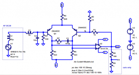
Here's a redesign of the first stage with a discrete input. Should do about 1.4 nV/√(Hz) as-is (about 10.5 dB better than now), could go lower if you were to parallel multiple transistors. You can also try BC327 if you don't have any 2N4403 on hand. Simulated PSRR looks good enough that no particularly low-noise supplies should be necessary, but you can include 100R - 100µ on both rails if you want to.
Leave C3 in to use as shown. DC offset is not likely to be super huge but could easily be several hundred mV.
BTW, someone move this to Analogue Source please.
Have an NJM2068 on hand? That should be a ~3 dB improvement already.
X2 should get a little 100n bypass cap across V+ - V- at least.
Here's a redesign of the first stage with a discrete input. Should do about 1.4 nV/√(Hz) as-is (about 10.5 dB better than now), could go lower if you were to parallel multiple transistors. You can also try BC327 if you don't have any 2N4403 on hand. Simulated PSRR looks good enough that no particularly low-noise supplies should be necessary, but you can include 100R - 100µ on both rails if you want to.
Leave C3 in to use as shown. DC offset is not likely to be super huge but could easily be several hundred mV.
BTW, someone move this to Analogue Source please.
Attachments
Last edited:
Thanks for the feedback
Hallo folks,
Thanks for your responses! A few answers to your questions:
1. Rayma, since I just wanted to reproduce a circuit of John Linsley Hood, I did not try or consider any modifications (such as shorting C2 or using an inverting topology for stage 1).
2. MarsBravo: there were no specs for the circuit published in the EW&WW 1993 article, and I don't have the documentation of the Hart Electronics kit. David Hembrow has built the kit in a remote past; he may have more information about the circuit. The EW&WW issue can be downloaded from americanradiohistory.com.
3. Stephan: Nice to hear from you! (I know your website and consider it very interesting). No, I don't have NJM2068 i.c.'s, although there are both 2N4403 and BC327 transistors in my junkbox (rather, attic!). As you predict, I expected the circuit to be very noisy, but for reasons I don't understand, this turned out to be not the case (as was reported both by Linsley Hood himself and by David Hembrow). Apparently, JLH designs can produce rather poor simulation data, but subjectively nice sonic results. I do not have much circuits for comparison, but possess a Ben Duncan-designed MC preamp with shunt feedback based on 3 op-amp circuits with discrete transistors per channel (as published in the magazine ETI) and a Curcio Daniel MC preamp with valves (and passive RIAA equalization). Both preamps date from the 1980s and are much noisier than the JLH circuit. Regarding the power supply: my preamp is fed by a classic Sulzer regulator (as published in The Audio Amateur 2/1980). If you ask: Why? I can only answer: since I had the parts for this reg in my junkbox.
Finally: Apologies for starting this thread in the wrong section of the forum. Hopefully, a moderator can move it to Analog Source.
Greetings, arensattic
...short C2...
C2 and C2 define a 12dB/oct subsonic filter which is very wise on some systems.
I don't think the LM833 (copycat '5532) is the bee's knee for MC hiss levels, but I don't doubt it is a competent design and may serve as well as arensattic says.
John used two LM833 op-amps
He wrote about a fet input IC2 though.
Attachments
C2 and C2 define a 12dB/oct subsonic filter which is very wise on some systems.
I don't think the LM833 (copycat '5532) is the bee's knee for MC hiss levels, but I don't doubt it is a competent design and may serve as well as arensattic says.
Using C2 as a filter component is pretty flawed - its electrolytic, so the tolerance will be poor, and it will age changing value substantially. It should be made so large in value it has no effect on the circuits response, and contributes negligible capacitor distortion. A separate high-pass filter with at least 3 poles is needed for a good subsonic filter which lets bottom octave through and yet can knock down ~10Hz arm resonances by a decent amount. That filter needs stable components to set its time constants, not electrolytics.
Which is peculiar since the Ben Duncan construction in particular seems to be noted for its low noise. It's the one from 1984, right - not the 1989 version with the SSM2016 input and all? Suffice it to say, if something with a 5532 up front makes a quieter MC pre than a construction that would be expected to have performance in the right ballpark for this task, something is very wrong.3. Stephan: Nice to hear from you! (I know your website and consider it very interesting). No, I don't have NJM2068 i.c.'s, although there are both 2N4403 and BC327 transistors in my junkbox (rather, attic!). As you predict, I expected the circuit to be very noisy, but for reasons I don't understand, this turned out to be not the case (as was reported both by Linsley Hood himself and by David Hembrow). Apparently, JLH designs can produce rather poor simulation data, but subjectively nice sonic results. I do not have much circuits for comparison, but possess a Ben Duncan-designed MC preamp with shunt feedback based on 3 op-amp circuits with discrete transistors per channel (as published in the magazine ETI) and a Curcio Daniel MC preamp with valves (and passive RIAA equalization). Both preamps date from the 1980s and are much noisier than the JLH circuit.
Stupid question: You did make sure to equalize signal levels, right? It's easy to have less noise if you have much less gain, too...
That one should be a good start - assuming you can keep it from oscillating, since the NE5534 is not unity gain compensated and requires an external compensation capacitor of at least 22 pF to remain stable all by itself, let alone with an emitter follower buffer. Choose pass transistors wisely (fT >=30 MHz at given operating current).Regarding the power supply: my preamp is fed by a classic Sulzer regulator (as published in The Audio Amateur 2/1980). If you ask: Why? I can only answer: since I had the parts for this reg in my junkbox.
Last edited:
Some responses to your feedback
Dear all,
I must be getting old. Both Salas and Stephan spotted an error in my message!
1. Salas, you are completely right. John Linsley Hood used a JFET input opamp for IC2. He did not specify the type, although in his 1993 article he mentioned TL052 and LF353. However, to my defense, I can say that the later Hart documentation of the circuit indicated that one could use LM833 or NE5532 both for IC1 and for IC2. SSM2139P was mentioned as an alternative for IC1, and LF351 or LF353 as an alternative for IC2.
2. An excerpt of the Hart documentation can be found at the following URL: hembrow.eu/personal/johnlinsleyhoodphono.html (If you surf to hembrow.eu, you will only find Davids webpages about bicycle parts. He sells bicycle parts and manufactures all kinds of baskets for bicycles).
3. Mark: it's of course completely true that electrolytics don't have eternal life, but they can be easily replaced (and selected with a capacitance/ESR meter...)
4. Stephan, you also spotted an error in my text. The MC preamp with discrete transistor circuits that I possess was not designed by Ben Duncan, but by Stan Curtis! It was published in the UK version of ETI (July-August 1981), and in the Dutch version of ETI one year later (July-August 1982). Since this was 37 years ago, my memory failed me... The circuit does not use any IC opamp at all, all opamps (3 per stereo channel) are made with discrete transistors (and the input transistors had to be selected for low noise. Since I did not have too many transistors at that time, my selection may not have been very effective") ).
).
Hope this clarifies things!
Best regards,
arensattic
Dear all,
I must be getting old. Both Salas and Stephan spotted an error in my message!
1. Salas, you are completely right. John Linsley Hood used a JFET input opamp for IC2. He did not specify the type, although in his 1993 article he mentioned TL052 and LF353. However, to my defense, I can say that the later Hart documentation of the circuit indicated that one could use LM833 or NE5532 both for IC1 and for IC2. SSM2139P was mentioned as an alternative for IC1, and LF351 or LF353 as an alternative for IC2.
2. An excerpt of the Hart documentation can be found at the following URL: hembrow.eu/personal/johnlinsleyhoodphono.html (If you surf to hembrow.eu, you will only find Davids webpages about bicycle parts. He sells bicycle parts and manufactures all kinds of baskets for bicycles).
3. Mark: it's of course completely true that electrolytics don't have eternal life, but they can be easily replaced (and selected with a capacitance/ESR meter...)
4. Stephan, you also spotted an error in my text. The MC preamp with discrete transistor circuits that I possess was not designed by Ben Duncan, but by Stan Curtis! It was published in the UK version of ETI (July-August 1981), and in the Dutch version of ETI one year later (July-August 1982). Since this was 37 years ago, my memory failed me... The circuit does not use any IC opamp at all, all opamps (3 per stereo channel) are made with discrete transistors (and the input transistors had to be selected for low noise. Since I did not have too many transistors at that time, my selection may not have been very effective
).Hope this clarifies things!
Best regards,
arensattic
You're being forgiven. I can't remember anything from that time either - too busy soiling my diapers, I suppose.4. Stephan, you also spotted an error in my text. The MC preamp with discrete transistor circuits that I possess was not designed by Ben Duncan, but by Stan Curtis! It was published in the UK version of ETI (July-August 1981), and in the Dutch version of ETI one year later (July-August 1982). Since this was 37 years ago, my memory failed me... The circuit does not use any IC opamp at all, all opamps (3 per stereo channel) are made with discrete transistors (and the input transistors had to be selected for low noise. Since I did not have too many transistors at that time, my selection may not have been very effective
So from here, we learn that you used some 2N3019s. I have been unable to find much about their Rbb', but judging from Cobo = 12p and r'b * Cc = 400 ps, maybe 30-odd ohms? (Makes sense for a medium power but highish beta transistor.) Not quite as low as you want for MC, but certainly in the ballpark - you should be able to hit 1-1.5 nV/sqrt(Hz) easily, so at least 12 dB beyond the capabilities of a 5532. You could try MPS8099, which Horowitz/Hill list with 8 ohms Rbb'... 2 in parallel should be close to as low as any MC pickup would ever need.
Looking at your page as well as the original article, there are a few things that I do not like and would consider changing:
1. Old 7815/7915 should be replaced by modern low-noise 78M15/79M15, which still easily cover the 120 mA required.
2. Module A-MC feedback network impedance is excessively low. You would need super low Rbb' input transistors and higher input LTP base current than the present ~1 mA to be able to take advantage of 56R/2R2. With your present input transistors you could probably go up to 10 times those values with a minimal (maybe 1 dB) noise penalty and a much happier output stage / power supply / channel separation. Or at least 300R/12R. (At ~2 mA tail current for the input LTP, even perfect noiseless transistors with Rbb' = 0 would be contributing ~26 ohms total. Seems pointless to shoot for less feedback R than about 1/3 of the sum of that + 2* Rbb'.)
3. Opamp circuits are lacking explicit dominant pole compensation (which would usually be B-C capacitance on Q5-12-19 - gut feeling says try 10-15pF and see what you get) and may as such prove unstable, especially if you have to sub in transistors. (You wrote you had trouble getting it stable? Not a huge surprise.) Maybe that's why the RIAA has C11 in there? 1970s board layout practices with wide spacing between V+ and V- presumably are not helping matters.
3. While having RC filtering on the positive power rail is basically a good idea, placing the capacitor on the MC input module when you've got a shared power and signal ground bus running all the way back from output to input is stupid. Do yourself a favor and run an extra wire alongside the existing ground from the midpoint between regulators to C2's (-) leg (either leg lifted or PCB cut, whichever you prefer). The design is also relying on loop gain for -PSRR and the 7915 only ever sees one measly 100 nF to ground on its output, all of which is... not ideal.
Ideally, I would have preferred to RC filter both V+ and V- twice, cleaning the rails up successively as you move back. The advantage of this approach is that you have less shared ground resistance and less critical stages with generally higher inherent noise level towards the output, plus the MC input won't mind if it only sees +/-10...12 V of supply. If you are clever, you'll be placing the dropper resistors to the left of output stage transistors Q6/7 and Q13/14, respectively (this makes a big difference in the MC module in particular, with ~5 mA vs. ~11 mA, allowing for more R / less C). This way you might get away with 47R (+470µ?) first and 220R (+220µ?) second.
With the silly low feedback resistor values out of the way, you could go a bit easier on RC filtering anyway.
4. The bias diode strings (D3-D5, D8-D11, D14-D17) should get a smallish capacitor in parallel. Try 10 µF perhaps (polarity observing). This tends to reduce output stage distortion quite a bit.
5. With all of this filtering business out of the way, I'd also consider higher input stage current for the A-MC module by scaling R3-5 accordingly. Maybe roughly a factor of 2 or so? Of course you need transistors with Rbb' low enough for this to be worth it.
6. Stan Curtis may not have had a local LW/MW station, as most practical circuits would include at least some kind of RF filtering at the input. In this case, some inductor in parallel with 100 ohms in series and 1-10 nF or thereabouts to ground perhaps.
Last edited:
Stan Curtis ETI-System Preamp
Hallo Stephan,
Thanks for your suggestions to improve the Stan Curtis design, I appreciate your feedback - although this subject may be a bit off-topic. The Curtis preamp is the subject of at least two other threads on this forum, namely ETI System A pre amp by Stan Curtis. Full article. and ETI System A preamp. Actually: some posts on diyaudio.com helped me to get this ancient design in working order: I tried to build a copy in the 1980s (when I was a postdoc in the biology department), then tried again in the late 1990s or early 2000s but encountered several problems (due to errors in the magazine article). Only after reading all diyaudio.com posts, I managed to build a third and nicely working prototype in 2015 (which probably proves that I am tenacious, but also not a very skilled constructor...).
I will definitely try some of your proposed improvements, but this may take some time (I often listen for months to a circuit, and test it with many favorite recordings before attempting a change).
When I started this thread, I promised to also report on the line-level preamp section of my latest creation. I hope to do this next weekend (since currently, I am busy with writing tasks for my employer).
Thanks also to the moderator, for moving this thread to Analogue Source.
arensattic
Linestage used in combination with JLH mc preamp
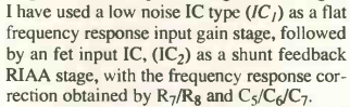
The JLH mc preamp should be followed by a volume control and line stage that can drive a power amplifier. I have revived (and slightly modified) a simple circuit that was once published in the Dutch magazine Audio & Techniek, and was called the P9. John van der Sluis, the designer of the circuit, used an opamp with a 2-transistor current source at the output, that forced some bias current through the output stages of the opamp. John employed one OP27 for each stereo channel, which I did not have in my junkbox. I replaced the two OP27s by a single LM4562 (Texas Instruments), reduced the circuit gain (from 11 to 4), and also reduced the resistor values in the feedback loop. The modified circuit can be used with a 10k log or 20k log volume control at the input. The sonic quality of the LM4562 is in my opinion quite good. To this post, I attach schematic, bottom view of PCB and top view of PCB.
The JLH mc preamp should be followed by a volume control and line stage that can drive a power amplifier. I have revived (and slightly modified) a simple circuit that was once published in the Dutch magazine Audio & Techniek, and was called the P9. John van der Sluis, the designer of the circuit, used an opamp with a 2-transistor current source at the output, that forced some bias current through the output stages of the opamp. John employed one OP27 for each stereo channel, which I did not have in my junkbox. I replaced the two OP27s by a single LM4562 (Texas Instruments), reduced the circuit gain (from 11 to 4), and also reduced the resistor values in the feedback loop. The modified circuit can be used with a 10k log or 20k log volume control at the input. The sonic quality of the LM4562 is in my opinion quite good. To this post, I attach schematic, bottom view of PCB and top view of PCB.
Attachments
- Status
- This old topic is closed. If you want to reopen this topic, contact a moderator using the "Report Post" button.
- Home
- Source & Line
- Analogue Source
- Simple preamp with MC and line-level inputs