Hi Matt,
Yes, those capacitors are the only difference between how I do these and what you did. Component selection can be critical, and the low frequency gain is so high on this that large surface area can certainly cause issues.
I would replace them with a quality electrolytic capacitor. Those are better than what was installed from the factory. You could use a bipolar one if you want. A 16V rating would be okay in this case because that capacitor only sees input bias and signals in the uV to mV level. Nothing wrong at all with a polarized capacitor either.
So now we are all a little bit smarter, thanks to your problems with this. We all gained something, so it wasn't a waste of your time. Betcha you never forget this lesson!
Best, Chris
Thanks for your help Chris! If this is useful to anyone else, then it's a win-win.
And um, yep, this one will stick with me for a long time. . . .
What's funny/ironic is that I usually do replace tants with low-leakage electrolytics. Sigh.
So would a Nichicon UKL be ok here?
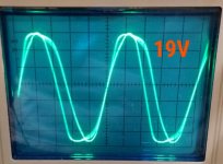
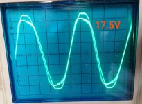
And I'm still a bit perplexed by the wave forms I'm seeing with a 1 kHz sine wave going to the phono inputs and being viewed on my scope through the tape monitor outputs (AC coupling). The clipping is greater on the positive side in one channel and on the negative in the other, i.e. they're reversed. There's also that odd semi-rounding of the one edge on two of the peaks. Having never made this adjustment, I'm not sure what to expect.
Attached are shots of what I'm seeing with 19V and 17.5V on the collectors of H405 and H406.
And um, yep, this one will stick with me for a long time. . . .
What's funny/ironic is that I usually do replace tants with low-leakage electrolytics. Sigh.
So would a Nichicon UKL be ok here?
And I'm still a bit perplexed by the wave forms I'm seeing with a 1 kHz sine wave going to the phono inputs and being viewed on my scope through the tape monitor outputs (AC coupling). The clipping is greater on the positive side in one channel and on the negative in the other, i.e. they're reversed. There's also that odd semi-rounding of the one edge on two of the peaks. Having never made this adjustment, I'm not sure what to expect.
Attached are shots of what I'm seeing with 19V and 17.5V on the collectors of H405 and H406.
Attachments
Hi Matt,
As you make your adjustment, one side will clip on positive peaks, then as you turn the control it will either get worse, or it may start clipping on the negative peaks. If it is clipping on both peaks, reduce the level you are sending in a little. I find it's easiest to do this adjustment when the signal is just below clipping when properly centered. So decrease the level until only one peak is clipping, then adjust that control (bias) until the other just starts to clip. Reduce the level still more if you are clipping on both peaks. WHat you want is a signal that is unclipped on both peaks unless you adjust that control. Then doing the other channel, the level should be already set to the right amplitude.
After this adjustment, I normally drop the level still more, then adjust the bias control for minimum distortion at 1 KHz. That's my fine adjustment, hard to do if you don't have a THD meter. The THD meter is easier to use than an RTX, or other kind of spectrum analysis. It's much easier to read the meter and set it for "minimum smoke".
-Chris
That clears it up, I think.
I don't have a THD meter, so I just set the pots using my oscilloscope. I noticed that adjusting them too much in just one direction away from center would cause some oscillation (a little higher frequency than the previous motorboating) just prior to the start of the clipping. Anyway, after the adjustment, I put the shorting plugs back in the phono inputs and listened through headphones. I heard a faint ticking in the right channel, so I tweaked the corresponding pot just enough to get it to stop. The right pot is now a little off center (1 o'clock as opposed to 12), whereas the left channel is centered. Seems fine to me.
I'll order those 1 uF electrolytics to replace the tantalums.
Thanks again.
Matt
It just might be the losses of the capacitors that stabilize the bias loop, although 1 uF tantalum capacitors are not very lossy (specified 120 Hz tan(delta) of the order of 0.03 or 0.04). A Nichicon UKL aluminium electrolytic should work fine then, with its tan(delta) of 0.07 at 120 Hz.
Both hypotheses seem a bit strange, though. The surface area hypothesis sounds unlikely because the motorboating is a low-frequency problem (Matt didn't see any high-frequency issues) and it mainly occurs with shorted input, so with one capacitor plate grounded directly and the other via 1 uF.
The losses hypothesis sounds unlikely because there is a 470 ohm resistor in series with the cap. A tan(delta) of 0.04 at 120 Hz for a 1 uF capacitor is equivalent to only 53 ohm effective series resistance, much less than the 470 ohm. Then again, the ESR tends to increase with decreasing frequency, so maybe it does dominate at the deep subsonic frequency of the motorboating?
Hi Marcel,
Okay, it wasn't fixed then.
The much larger size of the replacement capacitors at that point in the circuit could make it unstable due to the huge amount of low frequency gain. Tantalum capacitors are lossy considering they are a solid capacitor. A good electrolytic capacitor has about the same dissipation. Modern solid capacitors are much better in that regard. I generally measure performance at 1 KHz as it gives me a more realistic sense of how they will perform. What looks good at 100 or 120 Hz can fall apart at 1 KHz. They also have high distortion which I guess is a voltage thing with them. The only good tantalum capacitor is a wet slug type, the solid ones are just terrible for audio uses. They are also pretty poor when used in high frequency switching power supplies.
Would you care to throw out any ideas as to why removing a vastly superior film capacitor (although larger) and installing a much smaller but poorly performing part would correct the problem? I generally use film capacitors in this position as well, but they are much smaller and have yet to cause any problems. I ahev done a huge number of these over the years.
-Best, Chris
....what's the significance of the fact that the motorboating only occurs when the inputs are shorted?
In this amp, I have no clue.
And it clearly worked when new.
In "similar" amps which bias from output emitter (with cap bypass) to first base (and cap to jack), it is incredibly easy to end up with a big subsonic peak. And no practical cap-change fixes it, just chases it lower and taller. Combined with "any" other bass pole (supply bypass??) it can outright oscillate. More when input is shorted. And a super-speedy "fix" is 1k in series with the jack. This has other ill effects but makes a perfectly playable preamp.
Transistor gain has slight effect. Using high-hFE parts in a $9.98 phono preamp can do it. A backward transistor would probably make it stable (just like starving the amp did) but then it is a bad amp.
So I would re-re-check all caps and transistor. Right size, right way, well jointed.....
Would you care to throw out any ideas as to why removing a vastly superior film capacitor (although larger) and installing a much smaller but poorly performing part would correct the problem? I generally use film capacitors in this position as well, but they are much smaller and have yet to cause any problems. I ahev done a huge number of these over the years.
-Best, Chris
I already did when I wrote that the losses might stabilize the loop (ESR + 470 ohm causes a zero in the loop that has a stabilizing effect). I had something similar with an LM317 in my valve DAC: the DAC sometimes produced an audible beep until someone on this forum explained that LM317's may oscillate when the quality factor of their output decoupling is too high. I shunted the ceramic class 2 capacitors that I had used with a run-of-the-mill aluminium electrolytic and haven't heard a beep since.
However, in this case, it all doesn't add up. 53 ohm of ESR is much less than the 470 ohm that was already there. It could only help when the loop is at the edge of instability - which it very well might be, considering that it sometimes oscillates and sometimes doesn't. But I haven't a clue why it would be at the edge in the first place.
Hi Marcel,
I think that we are looking more at a simple case of feedback due to the electrode size on these capacitors. The gain is so high at low frequencies that it is probably super sensitive to any low frequency pick up.
Since replacing those with the Tantalum capacitors, and in the future with good electrolytic capacitors, the problem went away. The only thing that does make sense is the area of the input capacitors. With units I have worked on since the early eighties, I have never had this problem. In the early days I did replace the tantalum capacitors with Aluminum electrolytic capacitors and have never run into this. Therefore I don't believe it is capacitor type that is at the root of this. It's just stray signal pickup. An interesting test would be to temporarily cover the film capacitor with a grounded shield. That might answer these questions for us. I am not recommending the use of shields so that the over-sized capacitors can be used. Just investigating what the actual cause is.
Thoughts?
-Chris
Hi Chris,
Doesn't it seem odd to you that Matt sees the oscillations with inputs shorted rather than inputs open? If it were due to parasitic capacitive coupling to the oversized input capacitors, I would expect the biggest problems to occur with open inputs.
In any case, if your hypothesis is correct, then the circuit should work fine once the capacitors are replaced with physically smaller capacitors.
If my hypothesis is correct, then the circuit will still have a large resonance at some deep subsonic frequency once the capacitors are replaced with somewhat more lossy types, at least when it is driven from a very low impedance source. Besides, since you have the experience that the circuit should not require lossy capacitors, there must then still be something wrong somewhere (faulty component, loose contact, whatever). If it is something that is not common to left and right, that will probably mean that one channel will work fine and the other not.
So I'd suggest to measure the frequency response driven from a low impedance on both channels from whatever frequency it used to motorboat on up to 20 kHz. If it looks fine on both channels, then everything is well. If not, then we have to take it from there.
Best regards,
Marcel
I already did when I wrote that the losses might stabilize the loop (ESR + 470 ohm causes a zero in the loop that has a stabilizing effect).
(...)
However, in this case, it all doesn't add up. 53 ohm of ESR is much less than the 470 ohm that was already there. It could only help when the loop is at the edge of instability - which it very well might be, considering that it sometimes oscillates and sometimes doesn't. But I haven't a clue why it would be at the edge in the first place.
Having another look at the schematic, I don't see how the ESR of the input capacitors could cause a zero in the loop gain, so my hypothesis goes down the drain. Nonetheless, I still think it a good idea to check the frequency response on both channels, just to be sure it is not at the edge of oscillation due to some unknown defect.
I've been following this discussion (sort of, as you both have worlds more experience and knowledge under your belts). The one thing we know is that putting the tantalums back in the circuit did stop the motorboating. If size was the issue with the Panasonic film caps, then I should be fine with smaller Nichicon UKLs. But there is an "if." So when I order the UKLs, I also want to get a few plan B caps that would be the closest possible approximation to what the tantalums do right, in addition to being small, that might be playing a role here. A much smaller stacked film than the ECQ Panasonics?
Hi Matt,
Yes. Those are what I use (stacked film). I have often said that your replacement components should not be any larger than the originals, and this is for good reason.
Hi Marcel,
I have tested the phono stages after the work is done to verify response and THD. They don't deviate that much, given their simplicity. But I don't know if Matt as a reverse RIAA filter network. I do see the value in what you are thinking about in this case. My current belief is that the larger capacitors simply picked up more signal causing a very low frequency oscillation. Shorting the inputs would generate a charging shock in the base circuit. Maybe that "bell" just wants to ring that low in frequency. There is certainly enough low frequency gain available. Nothing else seems to work as an explanation. So I'm saying that the system gets an impulse from being shorted, and the large capacitors can pick up more stray noise to continue the oscillation (=motor-boating). Beyond that, I am at a loss to explain the way it is acting.
-Chris
Hi Chris and Matt,
You can also measure the response of a phono preamplifier without using a reverse RIAA network, just with some resistive attenuators. Measure one point per octave and compare the results with the theoretical values. That's the way I've always done it; I'm sure it is more tedious, but when you only measure phono amplifiers once per decade, that's OK.
In this specific case the purpose of the measurement is to check for big subsonic peaks or other gross errors, so there is no need to measure very accurately. Just very slowly sweep the frequency and see if there are any weird bumps in the subsonic region. If not, check whether the gain drops with roughly the correct slope between 50 Hz and 20 kHz.
Regards,
Marcel
The UKLs didn't solve the issue. In fact, when I swapped them back out for the tantalums, the motorboating was present with those as well. So it would seem that something had changed when I first reinstalled the tantalums that stopped the problem, but not putting in the caps themselves.
When I installed the UKLs I was careful not to make any other changes: I unscrewed the board, tipped it out at a 90 degree angle with the chassis, installed the new caps, tipped the board back, and screwed it in. The only thing I can think of that could have changed, even slightly, was the board and it's relation to the wiring running behind it. I mention this because the proximity of the board to that wiring and the section of chassis behind it is the only way that I can stop and start the motorboating: With the board tipped out at a 90 degree angle, there's nothing, but as I tilt it back toward where it's supposed to sit, the motorboating will consistently begin when it comes within less than an inch.
I've tried prodding the wiring, pushing it away from the back of the board, while the motorboating is occurring. And it does sound as if this causes the frequency and amplitude to change, though the wires are all grouped so closely together that it's difficult to tell which might be responding.
Anyway, I'll continue to investigate.
That's a pity... If I were you, I would look again for poor solder joints or tiny fractures in PCB traces. If that doesn't help, take your scope and a 1:10 probe and measure the waveforms on all nodes you can access on both the left and right channel. Look for suspicious differences between left and right and for anything that doesn't make sense. Of course you can also take pictures of the waveforms and post them, maybe they give someone on this forum a clue as to what is going on.
Thanks Marcel. It certainly is odd. The fact that the problem cleared up temporarily when the old caps were reinstalled leads me to believe that the cause is likely the solder joints for those caps and any near to them, the wiring coming to and from the board, and/or the wiring running behind it. Nothing else changed.
- Status
- This old topic is closed. If you want to reopen this topic, contact a moderator using the "Report Post" button.
- Home
- Source & Line
- Analogue Source
- Pinpointing the source of hiss in a phono stage