I mean the 200uF C0 in the RIAA correction.
Then it's C1 in the LTspice schematic. 220uF BP + 10uF ceramic in actual unit built.
It's probably not a big deal here due to the very low signal levels…….
That's exactly the case. Over the audio frequency band, the voltage the ceramic capacitor sees would be very low to have its nonlinearities come into play in a noticeable way. At higher frequencies, perhaps a hundred to a few hundred KHz out, the low ESL of a ceramic cap helps keep the impedance down.
MLCC Class II dielectrics are usually troubled by mechanically induced noise (microphony), though, and that might be a risk in this circuit position.
100nF 1206 Class I (C0G) caps should be OK as a bypass, without any such problems.
A simple way of testing suspected piezoelectric parts being used in a wrong place is by tapping the PCB with the handle of a screwdriver while listening to the speakers. As long as the tapping doesn't make its way to the speakers there is little to worry about.
You have not stated the level of complexity you want to consider.
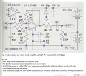
There is this one that you can evaluate. It is from the Linear Systems LSK489 app note. Another one on my list to do, but I am thinking, I might expand and add in a DC servo so that you can eliminate C5. It is possible to have a dual footprint and use a much cheaper jfet such as a 2sk209 and maybe cascode it as many have done.
There is also syn08 HPS designs to consider, but many more components and smd. There is a thread on the latast HPS 6 designs too.
Home
Lots of threads & options to consider.
Attachments
Last edited:
Thanks for the infos. I saw syn08 HPS designs, impressive and quite complex.
Well, generally I would want to keep complexity limited and under control for various reasons such as noise, cost, size. However I realize that is not as easy to do and the power supply complexity is going to be a little more elevated. For now I started to put a schematic together to get a rough Idea on the cost and complexity and there is already a lot of stuff.
This project will be my first attempt to build a phono pre-amp, and probably not my last. I guess this will take a few attempts to get this reasonably right.
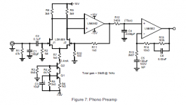
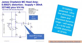
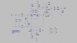
I opted to go with the James Chadwick MC Head Amp and the LM833 RIAA schematic for now. I have quite good simulation results with the JC MC when ganged with 8 pairs and feel this is a very good caditat to utilize. For the RIAA I use OPA1612 instead of the LM833. I realize power supply for the JC MC front end is absolute critical and quite touchy as DC voltage must be kept absolutely stable and noise free as well.
At this point I am expecting that eventually I will have to make adjustments to the gain. I will see once it is build. I put a few various switchable gain options to experiment with. For option selection, I can't come up with any better solution than using relays. I guess a necessary evil. But I will not want to relay on a single contact.
Well, generally I would want to keep complexity limited and under control for various reasons such as noise, cost, size. However I realize that is not as easy to do and the power supply complexity is going to be a little more elevated. For now I started to put a schematic together to get a rough Idea on the cost and complexity and there is already a lot of stuff.
This project will be my first attempt to build a phono pre-amp, and probably not my last.
I guess this will take a few attempts to get this reasonably right.I opted to go with the James Chadwick MC Head Amp and the LM833 RIAA schematic for now. I have quite good simulation results with the JC MC when ganged with 8 pairs and feel this is a very good caditat to utilize. For the RIAA I use OPA1612 instead of the LM833. I realize power supply for the JC MC front end is absolute critical and quite touchy as DC voltage must be kept absolutely stable and noise free as well.
At this point I am expecting that eventually I will have to make adjustments to the gain. I will see once it is build. I put a few various switchable gain options to experiment with. For option selection, I can't come up with any better solution than using relays. I guess a necessary evil. But I will not want to relay on a single contact.
Wow you have never built a phono amp, I recall I made my first LM381AN from the app note, it motorboated, I was in college and scrapped that one and went with a NE5533 (dual NE5534) instead.
I am unfamiliar with those designs, can you provide schematics or links to them.
There is also Bob Cordell Vinyl trak design to consider. There is also a few Doug Self designs, where he uses jumper blocks to set the gain. Gain setting is usually a one time deal, once you have your cartridge installed. Changing a cartridges is usually a lot more work (balance arm etc) than moving a jumper.
Good luck with your builds, post them so 8i can look at your results.
Hehe, well, for some reason I was always on the other side of the spectrum, working with much higher voltages and and signal amplitudes.
Actually this Phono PreAmp is not for me but a good friend. I had suggested to build it specifically for the Kleos but he wants some options to play with. In my books adding these options and the associated contact noise is not really helpful, but perhaps it is not as bad. Perhaps I am just over thinking this, as I have no experience working with such small signal amplitudes.
I studied syn08 designs a bit and noticed he does not seem to be afraid to put two contacts in series directly in the signal path. Neither does he put any supply cleanup. I guess perhaps all noise related things may not be as important as I think. He seems to get reasonably measurements altho I had always a hard time with noise figure measurements, I never got the same result twice.
Attachments
- Status
- This old topic is closed. If you want to reopen this topic, contact a moderator using the "Report Post" button.
- Home
- Source & Line
- Analogue Source
- MM / MC phone preamp needed