Hi,
My Marantz PM7200 phonostage has half a volt difference at the amplifier outputs. This doesn't surprise me as the amplifier seems poorly put together but I would like to try and solve this.
The output looks nice and clean on both channels and voltage supply is spot on for both channels but am stuck as to where to look next?
Thanks
Attachments
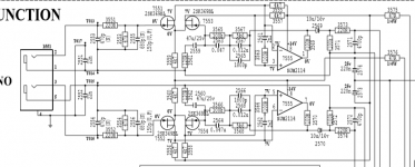
I looked up the datasheet of NJM2114, a bipolar OpAmp.
It is low noise and fast, but has significant allowable Input Offset Voltage (typical 0.2mV max 3mV), which, when amplified in a phono equalizer (very high DC amplification), can turn into 0.5V easily.
I agree, leave it as it is, as long as you have a coupling capacitor at the output.
Some people even want the offset to be at least some hundred mV in order to have the capacitors biased, for lower distortion. Just check if cap polarity is correct and turn around if necessary.
To be safe not to reopen the device too soon, you may want to recap and maybe add film caps in parallel to the electrolytics.
- Johannes
Assuming you mean the voltage at pins 1 and pin 7 of the NJM2114 are 0.5V different, it's probably poor JFET matching and not worth messing with. Note the 10uF/16V caps are there to remove any such offset.
Its the output of the power amplifier that is 0.5v different.
That´s how I read too, nothing wit DC diff. but one channel is o,5 volt (ac) louder than the other. You need an oscilloscope, and then feed the input with a mono signal. Then start measuring both channels in the phono amp from input to output to see, where the difference occurs. My best guess would be 1 of 3: One of the input fet´s is bad, one half of the opamp is bad, or one of the output caps (10uF/16v) has lost it´s capacitance resulting in deep bass missing in one channel.
Keep us updated")
Keep us updated
And this is a pretty reliable seller from Ireland (I´ve bought stuff there)
Semiconductor: 2SK369BL (2SK 369BL) - N-CHNL/J-FET / 40V / 10mA...
Semiconductor: 2SK369BL (2SK 369BL) - N-CHNL/J-FET / 40V / 10mA...
Its the output of the power amplifier that is 0.5v different.
If the DC is in the output of the power amp (on speaker connectors) then whatever goes on in phono stage does not matter (as long as the signal is treated correctly) - the power amp stage has a capacitor on its signal input

so whatever goes on before that is irrelevant regarding the current problem.
Last edited:
I must admit I read this when it was first posted and assumed it was an issue with DC offset of the phono stage... however
How are you testing and comparing the gain of the phono section? My first thought is that if you are feeding a test signal into the inputs then you may be feeding to much signal into the stage. That would require you to set the volume at an artificially low level and that is precisely where channel imbalances in pots are at their worst.
How are you testing and comparing the gain of the phono section? My first thought is that if you are feeding a test signal into the inputs then you may be feeding to much signal into the stage. That would require you to set the volume at an artificially low level and that is precisely where channel imbalances in pots are at their worst.
OK, finally coming back to this and I don't seem to be getting a signal out of the phono stage, every other input works as they should.
Taking voltage measurements with negative lead clipped to chassis, the +/- 15v are present but on the njm2114d all pins read +/- 15v. It's not dropping to 7v on pins 2,3,5,6 or 0v on pins 1 and 7.
What can cause this?
Taking voltage measurements with negative lead clipped to chassis, the +/- 15v are present but on the njm2114d all pins read +/- 15v. It's not dropping to 7v on pins 2,3,5,6 or 0v on pins 1 and 7.
What can cause this?
List all the pins, 1 to 8 and the actual voltage on each. You can't have -/+15 on all pins
+/- 15v on all pins, the input board uses the back panel as a common ground, at the minute the board is out for easy access and I have wired these all together and connected back to chassis.
Earlier in the thread (post #1) it seems it did at least work. Has any work been done or parts swapped since then?
I cobbled together an inverse riaa (got schematic off ESP) as I thought that the output at very low level from my function generator was not the best, that's the only difference I made
+/- 15v on all pins, the input board uses the back panel as a common ground, at the minute the board is out for easy access and I have wired these all together and connected back to chassis.
The devil is always in the detail
Take pin 3 (random choice). You can't have -/+15 volts on it, it has to be at some defined voltage (unless the stage is oscillating weirdly).
So is it +15 or -15 on pin 3, or is it alternating between positive 15 and negative 15 (which would be somewhat odd).
The same reasoning applies to all the pin voltages, they have to be one or the other.
- Status
- This old topic is closed. If you want to reopen this topic, contact a moderator using the "Report Post" button.
- Home
- Source & Line
- Analogue Source
- marantz Pm7200 Phono Stage Problem