Hello,
I am working on AIWA AD-M800 tape deck which was given to me as "just in need of new belts" and appears to have many other problems. One of them is high bias current in right channel which I can't lower with bias trap coil adjustment procedure. I don't know how to fix it; his is my first tape recorder to restore so I don't know many specific things yet.
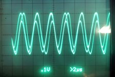
AIWA's bias trap consists of adjustable 22 mH inductor and 100 pF cap in parallel. Service manual calls for adjustment of the inductor such as reading at the recording amp's side just before the contour is minimal. Left channel went to less than 10 mV AC; however, right can't be lowered to less than 180-190 mV with the scope pattern shown at the first picture. Overall, the deck has problems with recording and can't finish autocalibration.
I measured voltages at "photo coupler" CP 301/CP302 which is downstream of the trap. It turns out bias voltage in the left channel is 420 mV AC and in right it's 7.1 V AC; the SM didn't say what it should be. Other voltages are quite different and few are just odd; they are below. All measurements were done in recording mode (REC and PLAY on pause).
Photo Couplers (numbering of pins same as at the picture):
1. Input from IC 359 pins 1/7: L. Ch AC=90 mV, DC=-10.5V; R. Ch AC=0.7-1.5 mV; DC=+1.96V
2. Output to ground: L. Ch. AC = 2 mV, DC=0 mV; R. Ch. AC = 0.8-1.2 mV, DC= +440 mV (!)
3. Input from bias oscillator: L. Ch AC=15.5 V; DC=+135mV; R. Ch. AC=15.7 V; DC= -300 mV
4. Output to bias trap and recording head: L. Ch. AC = 420 mV, DC=0 mV; R. Ch. AC = 7.1 V (!), DC=0 mV
5. Input from +5.2 V DC: both channels +5.32 V DC and 0 V AC;
6. Output to Q714 and pins 2/6 of IC359: L. Ch. AC=117 mV; DC= -5.29 V; R. Ch. AC=14 mV; DC=+720 mV
The photo coupler has numbers "7212F" on it and most likely is Silicon Sensor's MCD-7212F which looks same. The data sheet is here: https://datasheet.datasheetarchive.com/originals/scans/Scans-091/DSAHI000125977.pdf I don't know what should be operational voltage for the photo coupler diode which is supposed to be ON since deck is in record mode but it's completely different between channels.
I soldered out connections 3-6 as above leaving only first two that should operate the coupler, lifted traces and measured resistance in recording and stop modes between corresponding inputs and output pairs, 3+4 and 5+6. In all cases, they didn't conduct at all. Then desoldered both of 'couplers and installed one from the left (good?) channel into the right one. This didn't fix the bias trap problem, giving me same 180 mV AC and same picture on the scope.
Also, I can't explain +440 mV output of CP302. That output connected to ground through R474, checked it and sister R473 and both are within specs if measured against chassis ground.
Since it's 7.1 V bias current output in the right channel and only 420 mV in the left is it possible that in R channel bias current is too strong and the trap can't filter out all of it? However, if this is so why it's so big bias current AC voltage drop (15.5 V to 0.44V) in the supposedly good L channel within the photo coupler?
I don't know this circuit is working and how to fix it. Does anyone with more experience know what is wrong here?
The service manual is over 12 MB and of very high quality; here is the link: Free Service Manuals
Thank you.
I am working on AIWA AD-M800 tape deck which was given to me as "just in need of new belts" and appears to have many other problems. One of them is high bias current in right channel which I can't lower with bias trap coil adjustment procedure. I don't know how to fix it; his is my first tape recorder to restore so I don't know many specific things yet.
AIWA's bias trap consists of adjustable 22 mH inductor and 100 pF cap in parallel. Service manual calls for adjustment of the inductor such as reading at the recording amp's side just before the contour is minimal. Left channel went to less than 10 mV AC; however, right can't be lowered to less than 180-190 mV with the scope pattern shown at the first picture. Overall, the deck has problems with recording and can't finish autocalibration.
I measured voltages at "photo coupler" CP 301/CP302 which is downstream of the trap. It turns out bias voltage in the left channel is 420 mV AC and in right it's 7.1 V AC; the SM didn't say what it should be. Other voltages are quite different and few are just odd; they are below. All measurements were done in recording mode (REC and PLAY on pause).
Photo Couplers (numbering of pins same as at the picture):
1. Input from IC 359 pins 1/7: L. Ch AC=90 mV, DC=-10.5V; R. Ch AC=0.7-1.5 mV; DC=+1.96V
2. Output to ground: L. Ch. AC = 2 mV, DC=0 mV; R. Ch. AC = 0.8-1.2 mV, DC= +440 mV (!)
3. Input from bias oscillator: L. Ch AC=15.5 V; DC=+135mV; R. Ch. AC=15.7 V; DC= -300 mV
4. Output to bias trap and recording head: L. Ch. AC = 420 mV, DC=0 mV; R. Ch. AC = 7.1 V (!), DC=0 mV
5. Input from +5.2 V DC: both channels +5.32 V DC and 0 V AC;
6. Output to Q714 and pins 2/6 of IC359: L. Ch. AC=117 mV; DC= -5.29 V; R. Ch. AC=14 mV; DC=+720 mV
The photo coupler has numbers "7212F" on it and most likely is Silicon Sensor's MCD-7212F which looks same. The data sheet is here: https://datasheet.datasheetarchive.com/originals/scans/Scans-091/DSAHI000125977.pdf I don't know what should be operational voltage for the photo coupler diode which is supposed to be ON since deck is in record mode but it's completely different between channels.
I soldered out connections 3-6 as above leaving only first two that should operate the coupler, lifted traces and measured resistance in recording and stop modes between corresponding inputs and output pairs, 3+4 and 5+6. In all cases, they didn't conduct at all. Then desoldered both of 'couplers and installed one from the left (good?) channel into the right one. This didn't fix the bias trap problem, giving me same 180 mV AC and same picture on the scope.
Also, I can't explain +440 mV output of CP302. That output connected to ground through R474, checked it and sister R473 and both are within specs if measured against chassis ground.
Since it's 7.1 V bias current output in the right channel and only 420 mV in the left is it possible that in R channel bias current is too strong and the trap can't filter out all of it? However, if this is so why it's so big bias current AC voltage drop (15.5 V to 0.44V) in the supposedly good L channel within the photo coupler?
I don't know this circuit is working and how to fix it. Does anyone with more experience know what is wrong here?
The service manual is over 12 MB and of very high quality; here is the link: Free Service Manuals
Thank you.
Attachments
direct link to manual
The bias trap does not set the bias level, just prevents bias from back-leaking into the audio amplifiers.
This thing is a complicated mess. I *believe* some controller adjusts the LED in the photo-coupler to pass the correct bias. It is possible this coupler has failed. I don't find an obvious source for replacement.
This thing is a complicated mess.
YES!!
It is possible this coupler has failed. I don't find an obvious source for replacement.
Swapped couplers between channels and problem persists i.e. left channel is tunable to ~2 mV AC and right channel is tunable only to 190 mV AC.
So either couplers are both good or both failed in a different way.
I will replace a driver IC, IC 359 (LF359N) and bias control transistors, Q712-Q714, and report here.
Just working from the bit of circuit I can see it would appear that the opto is used as a variable resistive element to set the actual bias... and I suspect this is altered dynamically with the HF content of the music similar to Dolby HX Pro (which is not a noise reduction system).
You could as a test remove the opto's and fit (say) a 47k resistor in place of the lower part of the coupler (3 and 4 in your diagram) and just see if the bias is now equal.
Given that the bias is relatively high in voltage I wonder if that leads to possible degradation of the optos. Later implementations of this type of scheme used a small transformer as I recall to vary the coupling of bias to head.
Also make sure the record head isn't open circuit (or fractured lead wire to it) as that would see the apparent voltage shoot up.
... You could as a test remove the opto's and fit (say) a 47k resistor in place of the lower part of the coupler (3 and 4 in your diagram) and just see if the bias is now equal. ...
Also make sure the record head isn't open circuit (or fractured lead wire to it) as that would see the apparent voltage shoot up.
Did a test with 47K resistors and bias became equal, around 7 V in each channel. Checked the continuity of the recording head and cables through 20K resistors- both channels OK. Don't know how to determine if a head is worn though.
Meanwhile, replacement parts from Mouser arrived: a driver IC 359 (LF359N) and bias transistors. I replaced Q714 with KSA733 and socketed a new LF359N.
As a result, bias is each channel is equal and minimum 190 mV at the test point i.e. after the bias trap (use to be 10 mV one channel and 190 mV another). Before the trap it's now 9.6 V in one channel and 5.4 V in another (Fe tapes).
Without much hope, I run autocalibration with the Fe tape and ... IT WORKED! All steps were finished successfully and the "OK" lamp was on.
Before Q714 and IC359 replacement, autocal couldn't execute mid-range (8 kHz) and high-range (12 or 14 kHz) equalization adjustments. The autocal also successfully worked for CrO2 and Metal tapes.
Finally the deck now records reasonably well: at least it's close to CD source and plays well on itself and another deck. This was not possible before.
So it's a major leap forward.
Still some things remain to be done: bias is different between channels by a third or so. I suspect optocouplers; however, don't know if anything has to be done such as adding resistor to one channel. The deck should also be re-calibrated. I managed to break one of tunable inductors in the bias trap while rotating it although it seems to be working; don't know if it has to be replaced. However, it sounds more alive than dead now.
Last edited:
The 47k's seem to show that the problem of unequal bias could be in the drive to the opto's because earlier you mention swapping the opto's gave no change in the symptoms.
Normally you would adjust the bias manually (without using the auto cal) to give identical rec/play response on the two channels, for example equal level on 1k and 10k test tones at -20db level.
Before doing that you should ensure any playback equalisation adjustment is set correctly... which needs a test tape. If the deck has such adjustment and they have never been altered then you have to take it as being set correctly.
The dust core should be OK as long as you can get a definite minimum null in the adjustment.
/* Sounds like you hit a home run already, now that the Self-Cal is working. Good on ya'. Sorry I didn't get this posted in time to be of more use (started looking into it way back from your 6Jul post), but here are a couple bits anyway. */
+1 to Mooly and dhaen concerning the record head and wiring.
But I don't think the control could be dynamic (signal-variable). Remember, this is 1980 -- even the lowly 8-bit DAC (IC14) was relatively expensive then, the MCU is only 4-bit, and there doesn't appear to be any mechanism that would allow the processor to 'know' anything about the signal - level or frequency content or otherwise.
Also, if you get a suspicious measurement, you may want to follow the trace before unsoldering, because a few schematic mistakes turn up easily:
- IC17 on the mechancon board, for example, the schematic shows pins 11 and 13 swapped. We *know* because section '4/4's output is fighting with MCU output PG0 (pin 22), which otherwise gates the 3 other sections with PF1,2,3. Each of those 3 outputs drives a clk input on another IC, whereas one section 4/4 input (pin 11) is shown connected to *drive* the clk input of IC21!
- MPU pin 40 (PB3) has a 47k pullup to +5V, but its also wired directly to -5V. Still more strange -- the faulty short CROSSES OVER the lines to the adjacent pins, both of which are separately connected to -5V, too!
- The other 3 half-sections of LF353 (not the IC359 that you replaced) have their sections mixed up: Pins 1 and 7 are each an output, for sure, but the inputs straddle the 2 sections. The '+' input for IC352 is marked 'pin 3', which is the opposite section from the '-' input (pin 6) and output (pin 7). Same problem with IC353 and 355: '+' input designation (pin 5) is incompatible with '-' and output (pins 2 and 1). Probably easier/less-error-prone to measure at the de-mux outputs -- L-ch's are even #'d, R-ch's odd (if the schematic's correct), but use x10 or an FET probe or there'll be some droop.
Agree that the IC-pinout-arranged schematic takes some getting used to. Maybe all the time I spent squinting at the 8 and 12-panel foldout schems of the early generations of consumer VCR's back in the 80's gave me eyeball callouses -- this one doesn't seem so bad in comparison.
Gotta give 'em credit for attempting a design this ambitious (in 1980 !), but shee-zz ..
Good luck,
Rick
+1 to Mooly and dhaen concerning the record head and wiring.
But I don't think the control could be dynamic (signal-variable). Remember, this is 1980 -- even the lowly 8-bit DAC (IC14) was relatively expensive then, the MCU is only 4-bit, and there doesn't appear to be any mechanism that would allow the processor to 'know' anything about the signal - level or frequency content or otherwise.
Also, if you get a suspicious measurement, you may want to follow the trace before unsoldering, because a few schematic mistakes turn up easily:
- IC17 on the mechancon board, for example, the schematic shows pins 11 and 13 swapped. We *know* because section '4/4's output is fighting with MCU output PG0 (pin 22), which otherwise gates the 3 other sections with PF1,2,3. Each of those 3 outputs drives a clk input on another IC, whereas one section 4/4 input (pin 11) is shown connected to *drive* the clk input of IC21!
- MPU pin 40 (PB3) has a 47k pullup to +5V, but its also wired directly to -5V. Still more strange -- the faulty short CROSSES OVER the lines to the adjacent pins, both of which are separately connected to -5V, too!
- The other 3 half-sections of LF353 (not the IC359 that you replaced) have their sections mixed up: Pins 1 and 7 are each an output, for sure, but the inputs straddle the 2 sections. The '+' input for IC352 is marked 'pin 3', which is the opposite section from the '-' input (pin 6) and output (pin 7). Same problem with IC353 and 355: '+' input designation (pin 5) is incompatible with '-' and output (pins 2 and 1). Probably easier/less-error-prone to measure at the de-mux outputs -- L-ch's are even #'d, R-ch's odd (if the schematic's correct), but use x10 or an FET probe or there'll be some droop.
Agree that the IC-pinout-arranged schematic takes some getting used to. Maybe all the time I spent squinting at the 8 and 12-panel foldout schems of the early generations of consumer VCR's back in the 80's gave me eyeball callouses -- this one doesn't seem so bad in comparison.
Gotta give 'em credit for attempting a design this ambitious (in 1980 !), but shee-zz ..
I'd try to worry less about the optocouplers -- it's a closed-loop design that compensates for both initial part-to-part, and long-term deterioration. Plus you could spend more time trying to find a sub, than the total that you've already put into it.Still some things remain to be done: bias is different between channels by a third or so. I suspect optocouplers; however, don't know if anything has to be done ...
Good luck,
Rick
- Status
- This old topic is closed. If you want to reopen this topic, contact a moderator using the "Report Post" button.
- Home
- Source & Line
- Analogue Source
- Could someone help me with bias circuit of this AIWA cassette deck?