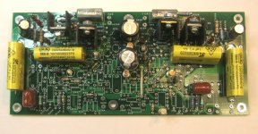
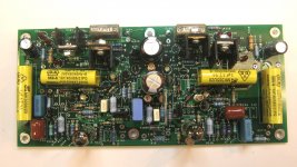
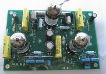
Attached is a view of a partially stuffed board that incorporates a hybrid RIAA preamp using a pair of submini Russian dual triodes with sand helpers, and a unique line stage utiizing a solid state triode emulator that acts like a gain-of-6 triode with 75 ohm output impedance. The fake triode is loaded with a cascoded current source to minimize stray capacitance and reduce distortion. The fake triode circuit shows impressively low distortion in simulation.
The top of the board contains the fully stuffed line amp. I'll be running some gain-phase plots on it tomorrow, along with time domain response. When I'm satisfied with the line stage performance, I'll finish stuffing the RIAA section and characterize that. This is one project that will likely make its way to this year's Burning Amp.
BTW, the board will be run from a switching adapter via a DC-DC converter of my own design.
Attachments
It's news, kinda lukewarm
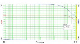
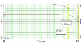
Attached please find the gain-phase plots for the two sides of the line amp. Response is zippy, but 40-45 degrees of phase margin leaves some room for improvement. Reducing the impedance feeding the output stage might help.
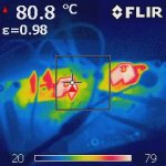
Also, check out a thermal picture of the line amp in operation - the main fets for the current source load need either a little less voltage and current, or some more heat sinking. I'd be satisfied with 60-70 degrees C instead of 80.
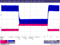
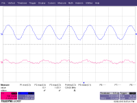
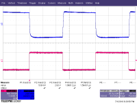
Finally, the time domain response shows a problem really needing fixing. As can be seen, the output waveform looks "wooly". Expansion of the waveform shows a ~120MHz parasitic oscillation. I suspect this might be coming from the current source load, and a judiciously placed ferrite bead might fix the problem.
More later, as I dig into these issues.
Attached please find the gain-phase plots for the two sides of the line amp. Response is zippy, but 40-45 degrees of phase margin leaves some room for improvement. Reducing the impedance feeding the output stage might help.
Also, check out a thermal picture of the line amp in operation - the main fets for the current source load need either a little less voltage and current, or some more heat sinking. I'd be satisfied with 60-70 degrees C instead of 80.
Finally, the time domain response shows a problem really needing fixing. As can be seen, the output waveform looks "wooly". Expansion of the waveform shows a ~120MHz parasitic oscillation. I suspect this might be coming from the current source load, and a judiciously placed ferrite bead might fix the problem.
More later, as I dig into these issues.
Attachments

Here's the board with everything that matters stuffed. The tubes light up, the bias LEDs light up, but the bias levels one the output stages of the phono stage needed adjustment. Done now, so I'll be doing some characterization of the phono stage tomorrow.
Attachments
I beefed up the heat sinks on the offending parts in the line stage, which brought case temperatures down into the 60's - acceptable in my book. Last weekend, I ran the gain-phase on the RIAA stages using the analyzer at work.
What I'm doing is reading out the gain vs. frequency from my scan, and entering selected points into into an Excel spreadsheet to get an RIAA deviation plot. RIAA deviation looks acceptable, but the points on my deviation graph are still bouncing around quite a bit from sample to sample. I probably need a better setup re noise pickup, more points/decade, and a heap more integration to smooth the graph out.
The other approach would be to go ahead and stuff the thing into a box to check out how it sounds, as the data trend so far shows low deviation from RIAA standard, even if the points bounce around a lot.
I have possibly another way of implementing the line amp stage that I'll be trying in simulation. If it pans out, I may do another spin on the board and mount all the hot parts in the line stage on a hefty common heat sink.
Last edited:
I'll be looking at improving the phase margin of the line stage of this preamp. Other than that, I'll be buttoning it up in a case (repurposed small HP case) with a custom DC-DC converter run from a wall wart. I'll be looking to use the low capacitance RIAA front end to optimally load an AT440MLB cartriidge, which is pretty fiddly as to the allowed loading capacitance. If I can tame the shriekiness of AT cartridge, the whole mess will be on display at this year's BA.
I use the AT150mlx and have found that total C loading, counting the tonearm wires, interconnect, and input C of the RIAA must be below 150pF. The generator of the 440 is very similar.
The easiest way to keep this under control is use an extremely low C interconnect. There are some Belden that are 15-20pF/ft and Blue Jeans Cable has their custom made (by Belden) “LC-1” is a breathtakingly low 12.2.pF/ft
The easiest way to keep this under control is use an extremely low C interconnect. There are some Belden that are 15-20pF/ft and Blue Jeans Cable has their custom made (by Belden) “LC-1” is a breathtakingly low 12.2.pF/ft
It appears that most of the AT MM cartridges have a similar sensitivity to capacitive loading. I have a handle on the capacitance of my tonearm wiring, and I should be below the limit with my preamp, as it has a liow capacitance triode input that is cascoded.
While I'm at it, I'll probably install some Beyer Dynamic step-up transformers to get low output moving coil capability. I have an AT low output MC cartridge in house, and a Hana SL (happy birthday to me!) on the way. I suspect that the Hana might kick the At's behind in terms of listenability, even though it has a humble aluminum cantilever and Shibata tip compared to the AT's Boron cantilever and fine-line tip.
Do you use the standard 47k loading, or some alternate value?
I just found the thread where I measured the capacitance of the tonearm/interconnects for my Denon DP-1100 turntable, and it's 95 pf. That likely means I won't be using any onboard loading capacitance, and I'll be making the interconnects from the inputs to my preamp board as short as I can.
Cool! Do you mind to share the schematics?
Best regards!
Agreed! Always eager to climb mountains for better sight... sound.
I did a re-do of this project using 6N3P-EV instead of the submini tubes. I also used a hybrid solution for the line amp instead of the all-solid state circuit as in the original project. The 6N3P-EV also has a shield between sections, which should reduce cross-coupling between channels.
There is some method to this madness, as with the addition of the 3rd tube, the filament voltages add up to nearly the output of a commonly available 19V computer power adapter. I'm thinking rather strongly of using a Baxendall converter fed by a buck converter to generate the B+. The Baxendall converter operates with a sine waveform. I've already breadboarded the Baxendall converter half of the DC-DC converter, and it works satisfactorily.
There is some method to this madness, as with the addition of the 3rd tube, the filament voltages add up to nearly the output of a commonly available 19V computer power adapter. I'm thinking rather strongly of using a Baxendall converter fed by a buck converter to generate the B+. The Baxendall converter operates with a sine waveform. I've already breadboarded the Baxendall converter half of the DC-DC converter, and it works satisfactorily.
Last edited:
Here are schematics for phono and line sections of the hybrid preamp utilizing 6N3P-E. 6N3P-E is several times cheaper than the submini tube I started with, easier to find, and of course, are compatible with std 9-pin PC sockets.
Resistors and p-channel fets are coming soon so I can finish populating this preamp and power it up for testing.
Resistors and p-channel fets are coming soon so I can finish populating this preamp and power it up for testing.
Attachments
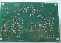
Here are top and bottom views of new board utilizing 6N3P-E. I chose to implement the line amp using a vacuum tube hybrid circuit rather than the original total solid state to avoid a big voltage transient from the line amp output during power-up. I will probably also use a capacitance multiplier on the B+ to get a slow rise characteristic (belt and braces). The last thing I want to do is to hook this preamp up to some poor, unsuspecting solid state amp and blow its input due to a power-on transient.
Attachments
Last edited:
- Home
- Source & Line
- Analogue Source
- Hybrid RIAA/Line Amp