Open loop gain is not 2*gm*R4.
But? I see two transistors each with gm, feeding R4 as a load after breaking the loop. Same load as for the common base view, same gain if R3 (degeneration) is zero.
R4 is the loop ..
You need to define open-loop gain for this type of amplifier. Forced input voltage vs output voltage is fairly clear.
So you think Syn's definition is fine ?
You have yet to offer your definition.
Well, I think Syn has to prove his formula.
Awe come on take charge tell us like it is.
Had to look up "take charge" in the dictionary.
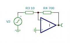
Have a look at fig. 4 of post 655 redrawn - picture attached.
(Syn wrote in # 658 that "the circuit can be considered as an inverting
negative feedback circuit" - it is an inverting negative feedback circuit.)
Do you still think that open loop gain of this is 2*gm*R4 ?
Have a look at fig. 4 of post 655 redrawn - picture attached.
(Syn wrote in # 658 that "the circuit can be considered as an inverting
negative feedback circuit" - it is an inverting negative feedback circuit.)
Do you still think that open loop gain of this is 2*gm*R4 ?
Attachments
Do you still think that open loop gain of this is 2*gm*R4 ?
What do you think it is?
R4 in this case is both the load resistor and the feedback resistor . Open loop in this case means to open the connection of R4 at the input node and connect it to ground instead.
So open loop gain is 2*gm*R4.
As the open loop gain is not very high (approx. x560 at 10 mA Ic), gain of the amp with closed feedback loop will be a liitle bit smaller than R4/R3
So open loop gain is 2*gm*R4.
As the open loop gain is not very high (approx. x560 at 10 mA Ic), gain of the amp with closed feedback loop will be a liitle bit smaller than R4/R3
In this simple transistor amp you can not take R4 out!
In your post #669 the textbook inverting amp is based on an OpAmp. An OpAmp does not change its open loop gain if you connect the feedback resistor to ground instead to the neg. input.
For the transistor amp it does. Without R4 (and without R5) the AC open loop gain is rc/re per transistor (rc being the bjt intrinsic collector resistance and re being Vt/Ic). With rc in the higher kOhm range, the gain will be large. But any load will change the gain significantly. Therefore R4 can not simply be omittted. When doing a complete math analysis, R4 will be part of the feedback equations but also part in the open loop gain calculation which is not the case if the open loop gain of the amp (e.g. Opamp) is not dependent on the actual load the amp has to drive.
I made a differential Duraglit simulation to find out the eventual benefits.
In a differential set-up, all even harmonics are greatly reduced, but to my feeling, these even harmonics are relatively harmless to the reproduced sound if below a certain level as is certainly the case here.
Measuring THD of SE and Diff versions showed differences up to almost 40dB, but closer exam learned that this was mainly caused by differences in H2.
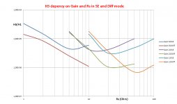
That's why I only examined H3, in relation to gain and Rs, for the SE and the Diff version, with all Amps set to an Ic of 6.25mA and tested with a 10KHz signal.
Since noise from both versions is so very low, noise penalty for a diff version is only 1 dB for Rs = 5 Ohm and 2 dB for Rs = 1 Ohm. Above 10 Ohm, Rs is the dominant noise producer.
The Image below shows H3 for 3 sets of gain:
Gain = 50x for 0,1mV Carts, tested with 10Khz 1mV,
Gain = 20x for 0.25mV Carts, tested with 10KHz 2.5 mV and
Gain = 10x for 0.5mV Carts tested with a 10KHz 5 mV signal.
The Diff version is slightly better for larger values of Rs, but all H3 values are almost within the one digit ppm range, which is excellent and no reason to switch to a Diff version.
Apart from a possibly small noise penalty, the only reason for a Diff version would then be the incomparable CMRR performance.
Hans
In a differential set-up, all even harmonics are greatly reduced, but to my feeling, these even harmonics are relatively harmless to the reproduced sound if below a certain level as is certainly the case here.
Measuring THD of SE and Diff versions showed differences up to almost 40dB, but closer exam learned that this was mainly caused by differences in H2.
That's why I only examined H3, in relation to gain and Rs, for the SE and the Diff version, with all Amps set to an Ic of 6.25mA and tested with a 10KHz signal.
Since noise from both versions is so very low, noise penalty for a diff version is only 1 dB for Rs = 5 Ohm and 2 dB for Rs = 1 Ohm. Above 10 Ohm, Rs is the dominant noise producer.
The Image below shows H3 for 3 sets of gain:
Gain = 50x for 0,1mV Carts, tested with 10Khz 1mV,
Gain = 20x for 0.25mV Carts, tested with 10KHz 2.5 mV and
Gain = 10x for 0.5mV Carts tested with a 10KHz 5 mV signal.
The Diff version is slightly better for larger values of Rs, but all H3 values are almost within the one digit ppm range, which is excellent and no reason to switch to a Diff version.
Apart from a possibly small noise penalty, the only reason for a Diff version would then be the incomparable CMRR performance.
Hans
Attachments
If so please show the complete analysis.
Professor Hajimiri from Cal Tech describes it in detail here. Breaking the loop is not just cutting a wire, the effect of load and source impedance have to be accounted for.
YouTube
I grovel at your feet oh Guru HansPlaying around with Richards Duraglit, I found that the circuit can just as well be seen as a Common Base but also as a Common Emitter.
Fig 1 below shows the well known topology
Fig 2 is exactly the same, but with all Gnd connections drawn together.
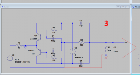
Fig 3 is the same as Fig 2, but with the Gnd connection now shifted to both emitters.
After all, since everything is floating when battery fed, this makes no difference in the functioning, other than that the circuit is now inverting from input to output.
Fig 4 is exactly Fig 3, but now with all components redrawn.
Thus the only difference between Fig 1 and Fig 4 is resp in non inverting and inverting. Apart from that, everything is still exactly the same: noise, distortion and gain with identical resistors R3 and R4.
I have meticulously checked that.
One could say that the topology represents an amp where the junction of the emitters is Vin+ and the junction of C1 and C2 is Vin-
So by just shifting the Gnd connection, the circuit morphs from a Common Emitter into a Common Base, without further changing anything to its performance.
 Great Guru Baxandall liked to turn circuits upside down to show equivalence too.
 It's way past my bedtime but ... this way of looking at it might be a simple explanation of Duraglit's much smaller current noise compared to the common or garden common base. Rni would be hfe times 2/gm which is the common base value ... ie that for common emitter.
These very simple circuits are unconditionally stable. In fact Han's variant of Duraglit is very similar to JC's wonky virtual earth but with much better PSRR.
I said earlier that at very high current, Duraglit's asymptotic 'gain' has it acting like a virtual earth and just shoving the input current into the load resistor .. which is the 'feedback' resistor in Han's version. It never quite makes it as load & feedback resistor are one & the same.
_________________
Hans, please post a circuit of your Differential Duraglit.
Last edited:
These very simple circuits are unconditionally stable.
Not always many years ago I thought an early microwave transistor (IIRC MRF901) might have low rbb. The simplest circuits all oscillated at 1GHz and it was not even stable in the Quantech without beads on all the test leads. The 1/f noise was gross so I gave up anyway.
Last edited:
No, absolutely notI found that the circuit can just as well be seen as a Common Base but also as a Common Emitter.
You forgot that the output voltage is not referenced to GND any moreFig 3 is the same as Fig 2, but with the Gnd connection now shifted to both emitters.
Attachments
- Home
- Source & Line
- Analogue Source
- Richard Lee's Ultra low Noise MC Head Amp