I think I may not have explained it well enough.
Output signal or gain depends on Ic, that's correct.
But in the noise calculation I have divided the output noise by the gain, to get the circuits input noise independent of gain.
I could have adjusted gain in all situations to the same amount by changing the output resistor, but for the few situations I tried to do this, it had marginally effect on the input noise, so I left the output resistor the same for all cases.
If you are convinced that this could introduce a significant error, I'm willing to redo the graphs.
But now coming back to the question concerning relation between Y axis and S/N.
For a given Cart with a certain certain Rs, the graph shows a relative noise change of X dB when changing Ic.
The S/N for this given Cart will then change by -X dB for this change in Ic.
As mentioned as an example, when going with a 40 Ohm Cart from 5 mA to 20 mA, S/N will become 0.25 dB worse independent of Vout at 5cm/sec@1KHz.
When for a 1 Ohm Cart going from 2.77mA to 12 mA, S/N will improve by 3.2dB again inpendent of Vout at 5cm/sec@1KHz.
I'll think about, not sure why you made it so complicated when the textbook S/N ratio definition is rather straightforward. But then something that strikes me is that the S/N ratio fundamentally depends on the signal level. "S/N ratio of X dB" makes sense only if you add "ref. 0.4mV input". This is one reason why IMO S/N ratio is not a good metric for audio, and I just shared a few posts above my opinion that for the case of a MC head amp this S/N metric is straight useless and misleading.
Last edited:
I just shared a few posts above my opinion that for the case of a MC head amp this S/N metric is straight useless and misleading.
I just remembered that when I first started working I looked at a Keithley electrometer manual and saw noise figure re: 10**12 Ohms and thought WTF.
I just remembered that when I first started working I looked at a Keithley electrometer manual and saw noise figure re: 10**12 Ohms and thought WTF.
But I guess it was shunted buy the electrode capacitance of a few pF?
My previous images were meant to show the relative change in dB when changing the collector current for a given Rs.I'll think about, not sure why you made it so complicated when the textbook S/N ratio definition is rather straightforward. But then something that strikes me is that the S/N ratio fundamentally depends on the signal level. "S/N ratio of X dB" makes sense only if you add "ref. 0.4mV input". This is one reason why IMO S/N ratio is not a good metric for audio, and I just shared a few posts above my opinion that for the case of a MC head amp this S/N metric is straight useless and misleading.
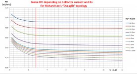
Now everything together in one image, showing the noise in nV/rtHz for all shown combinations in collector current and Rs, enabling the calculation of S/N for a given Cart.
I have no prejudice against S/N for a phono amp, it's a good indicator how noisy the amp is.
When it is in dB-A after Riaa, that magnitude gives a clear sign of how silent a phono amp is, reasonably matching your hearing perception.
65dB-A is the bottom line, 75dB-A is very good, and above doesn't bring much benefit because being way below your hearing limit at normal listening levels with the PU arm in the air.
For a S/N figure for a flat MC Head amp, 7.9 dB should be subtracted from the above figures, so resp 57.1dB as bottom line and 67.1dB as very good.
So for a 0.1mV 3R AT36E cart, looking at the image, noise at Ic=8mA is 0.28nV/rtHz
This gives a flat S/N of 20*log(1e-4/(141*0.28e-9)) = 68.1dB flat or 76.0 dB-A after Riaa and A-weighting. More than excellent.
For a Dynavector DV23R with 0.2mV and 35R, according to the image, noise at 4mA is 0.85nV/rtHz.
20*log(2e-4/(141*0.85e-9)) = 64.4 dB flat or 72.3 dB-A, which is still very good for this Cart.
It will be hard if not impossible to find anything bettering this figure.
Hans
Attachments
To see what the Formula from #541 does for the above examples with the AT36E and the Dynavector, two Carts at both ends of the spectrum, here again a calculation along that way:
S/N = 20*log[17.7e3*(Vcart/(Sqrt(RTI^2+Rs/60)]
Vcart the output in mV @5cm/sec/1KHz,
RTI the Amps equivalent input noise in nV/rtHz without Cart
Rs the Carts source resistance in Ohm.
For the AT with 0.1mV and 3R I used 8mA collector current, were noise with 0.1 Ohm, thus without Cart, is 0.19nV/rtHz.
Calculation then gives 20*log[17.7e3(0.1/(sqrt(0.19^2+3/60)] = 75.6 dB-A
For the Dynavector, 0.2mV and 35R, I used 4mA, were noise without cart is 0.21nV/rtHz.
20*log[17.7e3(0.2/sqrt(0.21^2+35/60)] = 73 dB-A
Both calculations are within +/- 0.7dB, also covering the span for all other combinations that I exercised.
Quite accurate IMO because none of the ultra complex behaviour of the "Duraglit" topology was taken into account.
I further investigated Scotts comment for high impedance MC amps, where a resistor is used to terminate the Cart.
A termination resistor has two effects, it reduces the output voltage in a linear way but also the combined resistor noise with a sqrt.
So for a termination 10 times Rcart, the effect is only a worsening in S/N of 0.4dB and even for a termination of 4 times Rcart, the effect is just 1dB loss in S/N, but this only for a completely unrealistic noiseless amp.
In practice the effect will be much smaller, reason to not include this in the formula.
Another comment was to include input noise current, contributing to additional voltage noise. This is easy to inplement with the addition of In.
When unknown, or for a Fet inut, simply set In to zero.
This alters the formula into:
S/N = 20*log[17.7e3*(Vcart/(Sqrt(RTI^2+Rs/60 +In*Rs^2)]
Vcart the output in mV @5cm/sec/1KHz,
RTI the Amps equivalent input noise in nV/rtHz without Cart
Rs the Carts source resistance in Ohm.
In the input current noise in nA
S/N outcome is after Riaa and after A-weighting.
IMO it is safe to assume that the outcome of this formula is accurate to within +0dB/-2dB.
Hans
Not everyone's SPICE has that feature?You can also write "noiseless" after the resistor part value.
Spice 3 does not seem to have it:
< SPICE Circuit Components >
LTspice has it.
ngspice has it, chapter 3.2.1 Resistors, page 71/637
< http://ngspice.sourceforge.net/docs/ngspice-manual.pdf >
ADS has noise=yes|no
< SPICE Circuit Components >
LTspice has it.
ngspice has it, chapter 3.2.1 Resistors, page 71/637
< http://ngspice.sourceforge.net/docs/ngspice-manual.pdf >
ADS has noise=yes|no
Spice 3 does not seem to have it:
We didn't have it either, partially because, "designer forgets noiseless flag and circuit tapes out with "noiseless" resistors."
")
Set the tempco of the resistor to zero ppm per Kelvin. Set the temperature of the resistor to zero Kelvin. Done. Yes LTSPICE allows you to individually set the temperature of every device.
But they already have a noiseless flag.
I'm not sure if that has an effect on noise. That was already in Spice 2,
but looking into the manuals, I had the impression that it was only for TC.
But methinks that LTspice gets it right.
While I'm at it:
Node collapsing is very tempting in Spice-like programs, as execution
time explodes with conductance matrix size.
When I have +60 Ohms in series with -60 Ohms, what noise do I get
for the complete branch? 1.4nV/rt(Hz) or 0?
I'll have to try that.
BTW, a 50 Ohm 12 dB attenuator with the other side open has about 60R.
A nice plug-on 1nV/rtHz calibrator.
cheers, Gerhard
Last edited:
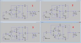
Playing around with Richards Duraglit, I found that the circuit can just as well be seen as a Common Base but also as a Common Emitter.
Fig 1 below shows the well known topology
Fig 2 is exactly the same, but with all Gnd connections drawn together.
Fig 3 is the same as Fig 2, but with the Gnd connection now shifted to both emitters.
After all, since everything is floating when battery fed, this makes no difference in the functioning, other than that the circuit is now inverting from input to output.
Fig 4 is exactly Fig 3, but now with all components redrawn.
Thus the only difference between Fig 1 and Fig 4 is resp in non inverting and inverting. Apart from that, everything is still exactly the same: noise, distortion and gain with identical resistors R3 and R4.
I have meticulously checked that.
One could say that the topology represents an amp where the junction of the emitters is Vin+ and the junction of C1 and C2 is Vin-
So by just shifting the Gnd connection, the circuit morphs from a Common Emitter into a Common Base, without further changing anything to its performance.
Hans
Attachments
Playing around with Richards Duraglit, I found that the circuit can just as well be seen as a Common Base but also as a Common Emitter.
Fig 1 below shows the well known topology
Fig 2 is exactly the same, but with all Gnd connections drawn together.
Fig 3 is the same as Fig 2, but with the Gnd connection now shifted to both emitters.
After all, since everything is floating when battery fed, this makes no difference in the functioning, other than that the circuit is now inverting from input to output.
Fig 4 is exactly Fig 3, but now with all components redrawn.
Thus the only difference between Fig 1 and Fig 4 is resp in non inverting and inverting. Apart from that, everything is still exactly the same: noise, distortion and gain with identical resistors R3 and R4.
I have meticulously checked that.
One could say that the topology represents an amp where the junction of the emitters is Vin+ and the junction of C1 and C2 is Vin-
So by just shifting the Gnd connection, the circuit morphs from a Common Emitter into a Common Base, without further changing anything to its performance.
Looking at Fig. 4 there's an interesting perspective: the circuit can be considered as an inverting negative feedback circuit, however the loop gain is not easily there; the open loop gain is 2*gm*R4 which is not necessary large enough to approximate the closed loop gain to -R4/R3. The condition would be (2*gm*R4)*(R3/R4)>>1 or 2*gm*R3>>1 or gm>>1/(2*R3) and for R3=10ohm gm~500mS or a collector current over 12mA. The larger the Rs=R3 the lower Ic could be. I wonder how loop gain would look and any feedback loop stability condition, this needs spice. However, intuitively I would think this is unconditionally stable for all possible loop gains.
Looking at Fig. 4 ... the open loop gain is 2*gm*R4 ...
Open loop gain is not 2*gm*R4.
- Home
- Source & Line
- Analogue Source
- Richard Lee's Ultra low Noise MC Head Amp