You are right that the (dimensionless) SNR normaly is the ratio between input power / output power.Hans, that's for the symmetrical complementary version, calculations are for only half of that.
But in general, I have no idea what you are doing there and where is the discrepancy (if any) is coming from. Since simulation is so much easier, I am sure you could easily figure it out. SNR is by definition the ratio of signal and noise powers at the output, BTW.
But in audio to my best knowledge it is usually referred to some reference voltage, like 0.4mV for an MC Cart.
That means that it has to be compared to the noise voltage, to keep S/N dimensionless, right ??
This is what Wiki says about SNR in Audio:
Signal-to-noise ratio (SNR), is the ratio between the noise floor and an arbitrary reference level or alignment level.
In "professional" recording equipment, this reference level is usually +4 dBu (IEC 60268-17), though sometimes 0 dBu (UK and Europe - EBU standard Alignment level).
I'll come back to the noise levels of the half version of the preamp.
That was exactly what was unclear in your posting.
May I assume you are using the Maxwell topology ?
If not, could you be so kind to post the circuit diagram.
Hans
O.K. thanks.The german text on their webpage describes this 'automatic gain adjust' as already mentioned due to the gain dependency from genrator resistance. They had more High output MCs in mind as those have significantly higher Rgen. So the amp is compatible with Low and High output MC carts.
For all reason you mentioned with respect to high variability even between different LOMC cartridges there are different gain settings via jumpers on the board possible (low, medium and high - +12dB, +6dB and +0dB).
So bottom line 'automatic gain adjustment' is marketing blabla
Hans
Calculations are done in output powers SNR=10*LOG(Psignal/Pnoise)
Not sure what a Maxwell topology has to do here, the model for calculation purposes is a basic AC pi equivalent circuit, no Cbe and Cbc, no output conductance.
Not sure what a Maxwell topology has to do here, the model for calculation purposes is a basic AC pi equivalent circuit, no Cbe and Cbc, no output conductance.
You are right that the (dimensionless) SNR normaly is the ratio between input power / output power.
But in audio to my best knowledge it is usually referred to some reference voltage, like 0.4mV for an MC Cart.
That means that it has to be compared to the noise voltage, to keep S/N dimensionless, right ??
This is what Wiki says about SNR in Audio:
Signal-to-noise ratio (SNR), is the ratio between the noise floor and an arbitrary reference level or alignment level.
In "professional" recording equipment, this reference level is usually +4 dBu (IEC 60268-17), though sometimes 0 dBu (UK and Europe - EBU standard Alignment level).
I'll come back to the noise levels of the half version of the preamp.
That was exactly what was unclear in your posting.
May I assume you are using the Maxwell topology ?
If not, could you be so kind to post the circuit diagram.
Hans
O.K. accepted. I will stick from now on to S/N as the term that's always used for 20*log(Vref/Vnoise).Calculations are done in output powers SNR=10*LOG(Psignal/Pnoise)
That's what I also used in the formula in #541.
But at least its now clear why your SNR calculation differed so much from my S/N calculations in #577 and #581, that was comparing apples to pears.
Problem solved.
Now at last it's clear what model you are using.Not sure what a Maxwell topology has to do here, the model for calculation purposes is a basic AC pi equivalent circuit, no Cbe and Cbc, no output conductance.
Thank you.
Hans
I'm playing hooky from Beach Bum Honey Do issues so bear with me if I'm a little sporadic or miss important stuff.
My original document has 1/3 8ve plots of an Ortofon MC + Duraglit vs Ortofon MM into a good MM RIAA preamp.
MC + Duraglit noise measures QUIETER than the MM ... and the noise, being 'redder', is subjectively less yucky than the 'whiter than white' MM noise .. with RIAA etc.
Duraglit + most MC cartridges (certainly the Ortofons) will be quieter than most MMs cos MCs usually have more power output than MMs. MM inductance also prevents them using their full power output except at 1 frequency.
All in my original document .. which also has DBLT results which show Duraglit's advantages for World Peace & your sex life.")
OK. I confess DBLTs are almost impossible with a vinyl playback system though good 'Blind' is possible with some (?!) organisation.
___________
There are also some noise plots of various MMs with RIAA & Awt which show why you shouldn't use Awt to determine subjective noise if the spectrums are very different. Even if you have a spectrum analyser (easy today) you should LISTEN to the noise to determine subjective offense.
___________
I think we are almost there with the various Duraglit Specials. I need to sort out the subsonic LF issues and update my recommendations taking into account ZTX851/951. Also, there's a bit more work to be done on syn08's Solar Panel stuff.
For our next trick, MUCH HARDER, we should attempt getting MM noise to better Duraglit. This would involve smashing even more Golden Pinnae myths than Duraglit. Any takers? Guru Wurcer? ... though that should be in a separate thread.
This has been a fantastic thread. First, some beach bum improved JC's supadupa design by 4.4 dB for noise & 2dB for THD. But this pales into significance compared with syn08 & Guru Wurcer taking Duraglit to even greater heights of S/N & THD
Perhaps a better practical target is for MC + MCHA to be subjectively quieter than a good MM into a good MM RIAA preamp.To view things from the practical side, I have made a graph in the image below where Rcart and Vcart as inputs are telling how much noise RTI the MC amp may produce to achieve a 75dB-A S/N after Riaa correction.
My original document has 1/3 8ve plots of an Ortofon MC + Duraglit vs Ortofon MM into a good MM RIAA preamp.
MC + Duraglit noise measures QUIETER than the MM ... and the noise, being 'redder', is subjectively less yucky than the 'whiter than white' MM noise .. with RIAA etc.
Duraglit + most MC cartridges (certainly the Ortofons) will be quieter than most MMs cos MCs usually have more power output than MMs. MM inductance also prevents them using their full power output except at 1 frequency.
All in my original document .. which also has DBLT results which show Duraglit's advantages for World Peace & your sex life.
OK. I confess DBLTs are almost impossible with a vinyl playback system though good 'Blind' is possible with some (?!) organisation.
___________
There are also some noise plots of various MMs with RIAA & Awt which show why you shouldn't use Awt to determine subjective noise if the spectrums are very different. Even if you have a spectrum analyser (easy today) you should LISTEN to the noise to determine subjective offense.
___________
I think we are almost there with the various Duraglit Specials. I need to sort out the subsonic LF issues and update my recommendations taking into account ZTX851/951. Also, there's a bit more work to be done on syn08's Solar Panel stuff.
For our next trick, MUCH HARDER, we should attempt getting MM noise to better Duraglit. This would involve smashing even more Golden Pinnae myths than Duraglit.
Any takers? Guru Wurcer? ... though that should be in a separate thread.This has been a fantastic thread. First, some beach bum improved JC's supadupa design by 4.4 dB for noise & 2dB for THD. But this pales into significance compared with syn08 & Guru Wurcer taking Duraglit to even greater heights of S/N & THD
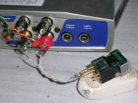
Circa 1980, the best transformer I found was the VERY expensive Denon for DL103. But even the unmatched WW 1981 Duraglit beat that for noise.how does the noise of the pre compare to an inline x10 transformer.
The quietest competing active device was the Stan Curtis designed, Ortofon MCA10 which IIRC, used JCs circuit. Stan claimed to have designed all good British electronics .. like JC claimed to have designed all good US electronics.
This was better all round than the mains powered Ortofon headamp.Duraglit's advantage over these two, the best of the rest, wasn't small .. 6-10dB depending on your chosen noise weighting.
The best I have ever achieved with a transformer was 1.7dB NF for a Calrec microphone preamp with either a large Lundahl or Sowter. In a different forum, I discuss using an even larger core
STEVENS AND BILLINGTON TX 103 MOVING COIL STEP UP TRANSFORMER | eBay
This would give 1.5dB NF if matched to the MC cartridge.
Duraglit, with its original matching recommendations, gives 3dB NF. With syn08 & Guru Wurcer's findings, we can beat 1.5dB NF
__________________________
Got any real-life evidence ? In da previous Millenium I looked at a lot of MC responses with loading and have yet to see any effect .. even into a virtual earth .. ie short circuit.macka said:In practice reducing the resistive loading of LMCC over a range of Cart Rs x 10 has a non linear effect versus frequency. This is also dependent of the Cart impedance. With suitable test record this can be verified. The take away is that the resistance loading should be adjustable for a flat response.
MC + Duraglit noise measures QUIETER than the MM ... and the noise, being 'redder', is subjectively less yucky than the 'whiter than white' MM noise .. with RIAA etc.
Duraglit + most MC cartridges (certainly the Ortofons) will be quieter than most MMs cos MCs usually have more power output than MMs. MM inductance also prevents them using their full power output except at 1 frequency.
Power has nothing to do with it just like the impedance matching had nothing to do with it, BTW no power is transferred to a virtual ground. You will have to explain your spectral terminology preferably with pictures. If you read the link from Hans, the guy measuring with an accelerometer show just how much mechanical energy is lost in the arm from the cart, the DL103R was particularly bad.
Checking the Stereophile website typical specs are more like this.
Signal/noise (A-weighted): 80dB (MM), 66dB (MC)
The ultimate limit contains a term sensitivity/sqrt(coil-R) and MC looses.
Gotta go back to Beach Bum stuff but ..
syn08. Yes. I did ASSume Duraglit would behave like a common or garden common base. Too good stuff to digest, ponder & reply in a short post.
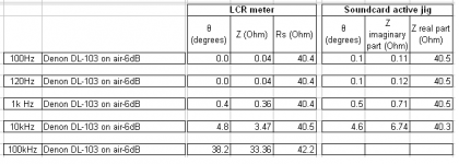
Guru Wurcer, where did you get DL103 at 12R? I've got 40R from my Jurassic notes. Spectral pics in my original document.
syn08. Yes. I did ASSume Duraglit would behave like a common or garden common base. Too good stuff to digest, ponder & reply in a short post.
Guru Wurcer, where did you get DL103 at 12R? I've got 40R from my Jurassic notes. Spectral pics in my original document.
Last edited:
Guru Wurcer, where did you get DL103 at 12R? I've got 40R from my Jurassic notes. Spectral pics in my original document.
Output Voltage
0.25 mV
Frequency Range
20 Hz to 45 kHz
Output Impedance
14 ohms
DL-103 did have a coil R change at some point in its 50 year life.
You know I never thought to run the Grado into a virtual ground, from sims the loading has virtually no effect on FR.
Calculations are done in output powers SNR=10*LOG(Psignal/Pnoise).
Ha,ha, that’s what you get when you don’t read the text and only look at pictures.
I was triggered by surprise as a Paslov reaction by the graph showing just 58dB at Rs 0.1 Ohm and never realised you were talking about power.
Quite silly, I should have known better.
Hans
On the load used to measure cartridge sensitivity front I have so far drawn a blank. There must be a DIN or other specification but not found it. Ortofon used 100 or 200 ohms but don't say what the cross over point is for changing. I assume 100 for all their low output models which are 3- 6Ohms. Will keep looking. May have to invoke George on this.
I enjoyed this thread. Very useful information.
But, I do not have MC and MM.
Maybe I will make dynamic microphone pre-amp. 1mV - 4mV/PA sensitivity and around 200 Ohm impedance. It must cheap as possible and using easily to find transistor and op-amp (in my country).
I appreciate, if someone can share transistor model that easily to find like BC337/BC327 which have low rBB?
Right now, I use this model:
.model BC337-40_kq NPN( IS=7.809E-14 Ibc=100f NF=0.9916 ISE=15f NE=1.4 Nk=0.55 BF=436.8 IKF=1.15 VAF=103.6 NR=0.991 ISC=6.66E-14 NC=1.2 BR=44.14 IKR=0.09 VAR=14 Rb=17.4 Kf=30f IRB=2.00E-04 RBM=8 RE=0.12 RC=0.05 Rco=3 XTB=0 EG=1.11 XTI=3 CJE=80p VJE=0.6657 MJE=0.3596 TF=620p XTF=1.5 VTF=2 ITF=0.5 PTF=88 CJC=1.306E-11 VJC=0.3647 MJC=0.3658 XCJC=0.455 TR=2.50E-08 CJS=0 VJS=0.75 MJS=0.333 FC=0.843 Vo=500 Gamma=4n Qco=8n Vceo=45 Icrating=800m mfg=OnSemi)
.model BC327-40_kq PNP( IS=2.077E-13 Ibc=230f NF=1.005 ISE=1.4f NE=1.3 NK=0.5 BF=475 IKF=.65 VAF=29 NR=1.002 ISC=2.963E-13 NC=1.25 BR=20.92 IKR=0.104 VAR=10 RB=17.4 Kf=240F IRB=1.00E-05 RBM=5.3 RE=0.14 RC=0.32 Rco=3.75 XTB=0 EG=1.11 XTI=3 CJE=115p VJE=0.9296 MJE=0.456 TF=500p XTF=3.25 VTF=2.5 ITF=0.79 PTF=80 CJC=2.675E-11 VJC=0.8956 MJC=0.4638 XCJC=0.459 TR=3.50E-08 CJS=0 VJS=0.75 MJS=0.333 FC=0.935 Vo=500 Gamma=10n Qco=8n Vceo=45 Icrating=800m mfg=OnSemi)
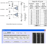
And in simulation a get Vin noise = 925pV/rt(Hz), but I not sure about Iin noise. Using 200 source resistor, I get output noise rms = 1.2596mV, gain = 70dB.
But, I do not have MC and MM.
Maybe I will make dynamic microphone pre-amp. 1mV - 4mV/PA sensitivity and around 200 Ohm impedance. It must cheap as possible and using easily to find transistor and op-amp (in my country).
I appreciate, if someone can share transistor model that easily to find like BC337/BC327 which have low rBB?
Right now, I use this model:
.model BC337-40_kq NPN( IS=7.809E-14 Ibc=100f NF=0.9916 ISE=15f NE=1.4 Nk=0.55 BF=436.8 IKF=1.15 VAF=103.6 NR=0.991 ISC=6.66E-14 NC=1.2 BR=44.14 IKR=0.09 VAR=14 Rb=17.4 Kf=30f IRB=2.00E-04 RBM=8 RE=0.12 RC=0.05 Rco=3 XTB=0 EG=1.11 XTI=3 CJE=80p VJE=0.6657 MJE=0.3596 TF=620p XTF=1.5 VTF=2 ITF=0.5 PTF=88 CJC=1.306E-11 VJC=0.3647 MJC=0.3658 XCJC=0.455 TR=2.50E-08 CJS=0 VJS=0.75 MJS=0.333 FC=0.843 Vo=500 Gamma=4n Qco=8n Vceo=45 Icrating=800m mfg=OnSemi)
.model BC327-40_kq PNP( IS=2.077E-13 Ibc=230f NF=1.005 ISE=1.4f NE=1.3 NK=0.5 BF=475 IKF=.65 VAF=29 NR=1.002 ISC=2.963E-13 NC=1.25 BR=20.92 IKR=0.104 VAR=10 RB=17.4 Kf=240F IRB=1.00E-05 RBM=5.3 RE=0.14 RC=0.32 Rco=3.75 XTB=0 EG=1.11 XTI=3 CJE=115p VJE=0.9296 MJE=0.456 TF=500p XTF=3.25 VTF=2.5 ITF=0.79 PTF=80 CJC=2.675E-11 VJC=0.8956 MJC=0.4638 XCJC=0.459 TR=3.50E-08 CJS=0 VJS=0.75 MJS=0.333 FC=0.935 Vo=500 Gamma=10n Qco=8n Vceo=45 Icrating=800m mfg=OnSemi)
And in simulation a get Vin noise = 925pV/rt(Hz), but I not sure about Iin noise. Using 200 source resistor, I get output noise rms = 1.2596mV, gain = 70dB.
Duraglit + most MC cartridges (certainly the Ortofons) will be quieter than most MMs cos MCs usually have more power output than MMs. MM inductance also prevents them using their full power output except at 1 frequency.
My power output is a concept used by electromagnetic transducer designers. V^2/Rdc where V is your 'voltage sensitivity' at whatever reference level (spl, velocity, oranges ..) you prefer.Power has nothing to do with it just like the impedance matching had nothing to do with it, BTW no power is transferred to a virtual ground.
It's a measure of potential S/N. You don't need to 'power match' to get this potential performance. eg you could use a non-inverting OPA or feed a Virtual Earth. As long as Rnv & Rni are very far from Rsource, and you have minimal EVIL resistors in the signal path, you can approach this potential. In both these cases, power transfer is minimal. The 'power match' is only coincidental for common or garden common base .. and I thought for Duraglit too until corrected by syn08 & Guru Wurcer
It's a synonym for your "sensitivity/sqrt(coil-R)".
Just had another look at the 1/3 8ve plot in my MicBuilders document.You will have to explain your spectral terminology preferably with pictures.
With constant bandwidth (eg 1/3 8ve), pink noise is flat and white rises at 3dB/8ve.
My curves show Duraglit + Ortofon MC noise droops slightly with frequency so 'reddish'. MM noise rises slightly with frequency so 'whitish' rather than 'whiter than white'. For that, the noise would have to rise at more than 3dB/8ve
Mea maxima culpa
It's bad in cartridges with high mechanical Z .. usually those with low compliance like the MC craze of the 80s... the guy measuring with an accelerometer show just how much mechanical energy is lost in the arm from the cart, the DL103R was particularly bad.
You can hear this energy acoustically ie with speakers off .. and the effect of tightening bearings, mounting screws & damping headshells ... also reducing tip mass. Oldies call this tiny tinny noise 'needle talk'.
An equal if not greater amount of energy is transmitted to the record. You can get a direct readout for this by having a second arm & cartridge playing the 'silent' runout groove and listen to the effect of different turntable mats.
IIRC, B&K had a number of papers on how to measure both these effects.
Last edited:
Can you confirm that your LTspice sims showed SNR for this 14R source, peaked at 12mA for a Duraglit with a single ZTX851/951 pair?I mentioned that for my 14 Ohm example 12mA was a minimum at least in LTSpice. More current and SNR degraded.
What rbb' & load did you assume?
Last edited:
I wrote BMC "Automatic gain adjust" simply means that gain is inversely proportional
to pickup coil resistance in a circuit like this.
(Voltage) gain in a current input like this is in fact inversely proportional
to pickup coil resistance, hope we agree. Yes, if the input resistance is
not zero it will have to be considered also.
The BMC preamp has no secret mechanism to adjust the gain other than
the gain change due to different pickup resistances. It is this alone that I
wanted to express.
I am however not in a position to prove your point "there are a loads of
0.5mV Carts differing in Rcart a factor 10 or 20".
to pickup coil resistance in a circuit like this.
Maybe you can explain in more detail.
Automatic gain adjust is not the same as inversely proportional to coil resistance.
From 1R to 30R this differs 20dB in gain for a 3R input.
And what happend when switching for a Cart with a lower or a higher output voltage ?
So I'm still intrigued and have no idea what this could mean.
Hans
(Voltage) gain in a current input like this is in fact inversely proportional
to pickup coil resistance, hope we agree. Yes, if the input resistance is
not zero it will have to be considered also.
The BMC preamp has no secret mechanism to adjust the gain other than
the gain change due to different pickup resistances. It is this alone that I
wanted to express.
I am however not in a position to prove your point "there are a loads of
0.5mV Carts differing in Rcart a factor 10 or 20".
DL-103 did have a coil R change at some point in its 50 year life.
I had bought mine around 2010.
It was a 40 Ohm
George
Attachments
- Home
- Source & Line
- Analogue Source
- Richard Lee's Ultra low Noise MC Head Amp