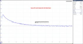
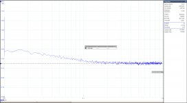
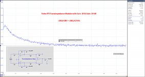
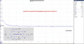
Here some results with the transimpedance module of my universal Diff in _ Diff/SE out Head Amp. I used a 1R input resistance simulating the Cart and with a Gain of 50 or 34 dB. Below the noise spectrum when fed with a 5W Nokia USB Wall Wart. No signs of Mains Harmonics are visible. Since the Bin Width is practically 1Hz, the Y axis can be read as dBV.
Noise RTI above 600Hz is -190.7dBV or 292pV/rtHz. When correcting for the 1R input resistance, noise for the bare transimpedance module calculates as 262pV/rtHz.
More detailed explanation to see at: Designing a universal diff-in/diff-out Head Amp
Hans
Noise RTI above 600Hz is -190.7dBV or 292pV/rtHz. When correcting for the 1R input resistance, noise for the bare transimpedance module calculates as 262pV/rtHz.
More detailed explanation to see at: Designing a universal diff-in/diff-out Head Amp
Hans
Attachments
That´s some nice S/N, Hans ")
Edit to my previous post. In my age, eyes aren´t what they used to be
Just looking at the DP-02 and seeing, that it had been repaired before, I automatically asumed, that it had been converted to LED´s. It had not. Standard miniature bulbs, where one was dead, and the other had almost no light. So after exchange of the 2 ´lytics and 2 new bulbs (12v/75mA), the Densen is fully functional again.
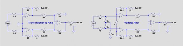
Having now also measured the noise RTI of the voltage amp, something peculiar is visible between the transimpedance and the voltage topologies.
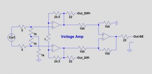
For a clear understanding of what I did, the first image below shows the two topologies, both using the same amp module.
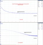
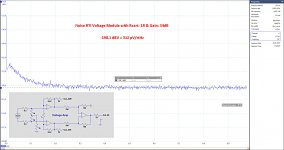
Second image shows the Transimpedance Amp's noise spectrum with a linear horizontal scale as well as with a logarithmic scale.
On the logarithmic version, noise below 600 Hz can be seen to have a slope of ca. -30dB/decade.
Exactly this same slope is visible in Syn08 image in #403, see here Richard Lee's Ultra low Noise MC Head Amp.
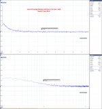
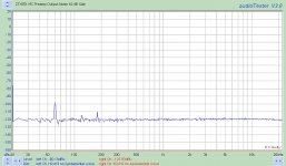
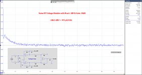
However for the voltage Amp, using the same amplifier module, the raised LF noise spectrum stops at a much lower frequency of ca 200Hz and has a slope of ca. -20dB/dec, see the third image for that.
I practice this has probably hardly any impact, but from a technical point of view I wonder why a virtual gnd topology produces a different pattern as a voltage amp.
In this case LT Spice is of no help, because both topologies show the same noise spectrum.
Hans
For a clear understanding of what I did, the first image below shows the two topologies, both using the same amp module.
Second image shows the Transimpedance Amp's noise spectrum with a linear horizontal scale as well as with a logarithmic scale.
On the logarithmic version, noise below 600 Hz can be seen to have a slope of ca. -30dB/decade.
Exactly this same slope is visible in Syn08 image in #403, see here Richard Lee's Ultra low Noise MC Head Amp.
However for the voltage Amp, using the same amplifier module, the raised LF noise spectrum stops at a much lower frequency of ca 200Hz and has a slope of ca. -20dB/dec, see the third image for that.
I practice this has probably hardly any impact, but from a technical point of view I wonder why a virtual gnd topology produces a different pattern as a voltage amp.
In this case LT Spice is of no help, because both topologies show the same noise spectrum.
Hans
Attachments
There's a short circuit in the circuit diagram of the above posting between both inputs of the lower transimpedance amp. This is not meant to be there.
Contrary to other projects where LT Spice was close to the measured results, in this very case the difference is large. Measured noise above 1kHz for Transimpedance and Voltage Amp, is >10% LOWER as simulated But LF noise is way above what LT Spice predicts.
The most likely component to my feeling causing this deviation with respect to the simulation are the ZTX851 and ZTX951 transistors, in this case all carrying 3.1mA.
On one hand the Rb seems therefore lower than the resp. 1.5R and 1.2R as used for both models, on the other hand 1/f, G-R or whatever noise is either not included in the ZTX models or completely wrong. The big difference between both Modules in LF noise seems only to be declared by a large spread in the knee point of said LF noise.
I have only one module of each type at this moment, but in the coming week I will assemble two extra boards to get more data to compare.
As already mentioned, with a 10Watt Apple USB power adapter a lot of mains harmonics do pop-up in the noise spectrum. But with a 5 Watt Apple USB adapter, model A1400 and also with a 5 Watt Nokia adapter, model AC-50E, the noise spectrum is just as clean as with the USB Power Bank. That the measured noise spectra are that clean is quite remarkable since the Head Amp while testing was not shielded by any casing. Modules and Mother Board with ground planes on both sides, so 4 gnd planes in total, plus a differential set-up do seemingly work effectively against mains pollution.
Hans
I would consider the spice models to be almost entirely fiction for noise performance as its really not the reason they make them. I am intrigued why Win needed an Ic of 25mA to get that early knee and you get it so low. But as Scott has mentioned, batch variability can be all over the place.
They still look pretty good when you take into account the application though.
They still look pretty good when you take into account the application though.
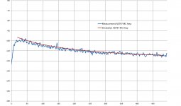
Hi Bill, Sorry, but I can't share your view on “simulation science fiction”. LT Spice is extremely accurate in predicting noise performance as long as the models are correct, see f.i. image below for a AD797 MC preamp.
And that's exactly what's the issue here. Wayne's model and my two different versions measure noise above 1kHz that's 10% less as what LT Spice predicts with the 1.5R resp 1.2R values for Rb. However when using the seemingly very low numbers in the original model, measured and simulated results are spot on, conclusion ?? But at the end 10% is less then a 1dB, so no big deal, but nevertheless.
But what's puzzling me much more is the LF noise. I've compared Wayne's noise spectrum with my Voltage Amp, now both spectra including Rcart = 10R and Rs = 1R, see both noise images below. Measured noise RTI above the knee point is almost the same (resp 487 and 467pV/rtHz). But Wayne's noise picture doesn't show any raised LF noise (Mind the different X axis, resp. 20Hz to 20kHz and 10Hz to 1KHz) Syn08's and my amps do show this ultimately -30dB/dec LF noise, although all with varying knee points. The difference in that is that Wayne only used the ZTX851, where the Lee and Curl amps are also using the complementary ZTX951 next to the ZTX851. So is the ZTX951 to blame for this LF noise, or did Wayne receive a golden batch ?? I'm anxious to see what the 2 extra boards from my small production will show in that respect. Hans P.S. I’m still looking forward to measure both your "Wayne" boards, as was proposed by you. .
Attachments
Last edited:
It was Horowitz and Hill who shined a spotlight on the very low measured noise of the Zetex transistors. Zetex themselves, and their new corporate owners (Diodes Inc) just call it a medium power high current transistor. There's no mention of noise anywhere on the datasheet. There's no guarantee its noise will be the same from unit to unit, or from week to week, or from fab to fab.
Skiers who venture "off piste", away from the marked trails, are on their own.
Medical doctors who prescribe medications "off label", to treat conditions other than the ones the FDA has approved the drug for, are similarly on their own.
It may also be true that designers who use a transistor (or its vendor supplied .MODEL) "off datasheet", are similarly their own.
For a larruping good time, telephone Zetex's application engineers and ask them for a better SPICE model which is less inaccurate when modeling noise. Expect to be asked about the volume of Zetex parts you have purchased this year & will purchase next year. That's how they prioritize their time.
All true what you said, but not as dramatic as it seems IMO and no reason not to use them.It was Horowitz and Hill who shined a spotlight on the very low measured noise of the Zetex transistors. Zetex themselves, and their new corporate owners (Diodes Inc) just call it a medium power high current transistor. There's no mention of noise anywhere on the datasheet. There's no guarantee its noise will be the same from unit to unit, or from week to week, or from fab to fab.
Skiers who venture "off piste", away from the marked trails, are on their own.
Medical doctors who prescribe medications "off label", to treat conditions other than the ones the FDA has approved the drug for, are similarly on their own.
It may also be true that designers who use a transistor (or its vendor supplied .MODEL) "off datasheet", are similarly their own.
For a larruping good time, telephone Zetex's application engineers and ask them for a better SPICE model which is less inaccurate when modeling noise. Expect to be asked about the volume of Zetex parts you have purchased this year & will purchase next year. That's how they prioritize their time.
What you need in this case is a test bench to select the ones with a low knee point, since noise above the knee point seems well defined with their very low Rb.
Hans
Bill,
Not sure if I understand what you are asking for. Are you referring to the last image with a 10R cart in comparance with Wayne's meaurement ? In that case, it's still the same voltage board as before but now with a 10R Cart. See below.
With Rcart = 10R, noise above the knee point was 467nV/rtHz with the voltage amp. To compare: with Rcart =1R, the transimpedance amp measured 288nV/rtHz and the voltage amp 312nV/rtHz (posting #1504) The noise of the voltage amp is always a bit higher because of the extra resististor Rs, in this case 1R, that is there to set the gain. Gain = 1+(2x24.5R)/1R = 50x
If this is not what you asked for, please let me know.
Hans
Attachments
Last edited:
Here you have the three together. All measurements are taken from the SE output.
Hans
P.S. the Diff to SE converter is a LT6233
.
Hans
P.S. the Diff to SE converter is a LT6233
.
Attachments
Last edited:
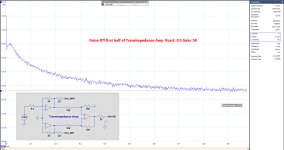
The very strong suspicion that the ZTX 851&951 transistors are having a large spread in their LF noise behaviour, was easily confirmed with my differential Transimpedance Amp.
One half could be set to an insignificant gain of 1 and the other half to a dominant gain of 50 and VV.
The two images below do indeed show a huge difference between the two halves of 25dB@20Hz, almost a factor 20 !
When using ZTX transistors, it makes absolute sense to test them in advance in a socket.
Hans
.
Attachments
Hans,
this finding confirms exactly what syn08 already experienced when testing various ZTX transistors. He found some that showed excellent noise behaviour for the flat as well as for the 1/f knee even better than the old Rohm low noise transistors and others that were also low in the flat region but showed the 1/f knee in the 500 Hz region. So the Rbb value seems to be somehow consistent between ZTX devices while the 1/f knee frequency shows a high variability.
So if really lowest noise is required, preselection is the only way to go. But even unselected they are still better than most of other available low noise types
What is the circuit that shows that behaviour? It couldn't possibly be the op amp array that is depicted above so often? I must admit that I did not follow this here closely for some weeks.
I have seen stronger than 1/f rise from too small input coupling capacitors that did not allow to short the bias network through the low-impedance DUT; or exactly 30 dB/dec from the leaky electrolytics that ac-shorted my CCS into the FET source, but I have never ever seen 30 dB/decade from transistors.
And the leaky capacitors all had 30 dB/decade, only with different corners.
Cheers, Gerhard
- Home
- Source & Line
- Analogue Source
- Richard Lee's Ultra low Noise MC Head Amp