If there are indeed some capacitors with let's say 330pF connected between primary and secondary side this may introduce some significant ground loop currents into your system. I assume the SMPS only powers the LEDs and that there is no connection to the ground of your amplifier nor the shielding box. Despite all the regulators in the chain, the -rail goes straight through to the final regulator and the -rail of the LEDs. If there is only 100 pF stray capacitance between e.g. the - rail of the SMPS and yor amp/housing this already will introduce about 4µA of 60Hz loop current. Higher harmonics are lower but impedance is also lower probably explaining also the 60 Hz harmonics.All true, but I still don't understand what has this to do with the mains frequency harmonics. The filtering is very good (and unchanged from when using a regular AC/DC wall wart), the extra linear regulator has very good line regulation at 60Hz, nothing seems to justify the observed behavior.
Question (serious). If you are using a wall-wart to power up an LED<>solar-cell array to provide a isolation in the syn08 Duraglit, surely its just easier to regulate the wall-wart down and feed the Duraglit directly since the wall-wart output is already floating?
I believe is you hunt around you can get linear wall warts with regulated outputs which can then be regulated down to the requisite 1.5V for the Duraglit.
Separately, on my JFET MC/MM amp, I have the 3.2VA transformer in the same housing and knew I was taking a risk with potential hum, but it is absolutely silent - I'm using one of the Talema blue toroids - They are now sold under various brand names (Mouser and Digikey carry them, RS here in the EU) and the stray mag fields are very low. The distance between the transformer and the MC front end is about 15cm in my preamp.
(one other point - is your LM317 not perhaps coming out of reg and you are getting ripple on the solar cell output?)
In the Duraglit the floating power supply is moving up and down with respect to ground carrying the full output signal. So haveing quite a distance makes the complete structure huge and hum and other interference is likely. For such lowest noise amps with floating supply systems, power supply and amp shold be very close with as short as possible leads in between and the complete structure should be shielded. Therefore having batteries or solar cell power supplies on board is ideal.
(as the LM317 current regulators are already DC powered by a pre-reg it's quite unlikely that in case of a too low voltage reserve will introduce 60Hz AC hum)
(as the LM317 current regulators are already DC powered by a pre-reg it's quite unlikely that in case of a too low voltage reserve will introduce 60Hz AC hum)
Last edited:
Kinda obtuse, but if you're not interested I won't bug you any more.
Chris
Sorry Chris I won't get all the details right. You might want to find Nyquist's original derivation of noise with the quantum mechanical corrections.
In the Duraglit the floating power supply is moving up and down with respect to ground carrying the full output signal. So haveing quite a distance makes the complete structure huge and hum and other interference is likely. For such lowest noise amps with floating supply systems, power supply and amp shold be very close with as short as possible leads in between and the complete structure should be shielded. Therefore having batteries or solar cell power supplies on board is ideal.
(as the LM317 current regulators are already DC powered by a pre-reg it's quite unlikely that in case of a too low voltage reserve will introduce 60Hz AC hum)
Sorry, I don’t understand this.
What is the difference between feeding a regulated DC into the durability and then regulating it down to the correct voltage. The wall-wart is isolated right?
Are you talking about a ground loop of some sort?
If there are indeed some capacitors with let's say 330pF connected between primary and secondary side this may introduce some significant ground loop currents into your system. I assume the SMPS only powers the LEDs and that there is no connection to the ground of your amplifier nor the shielding box. Despite all the regulators in the chain, the -rail goes straight through to the final regulator and the -rail of the LEDs. If there is only 100 pF stray capacitance between e.g. the - rail of the SMPS and yor amp/housing this already will introduce about 4µA of 60Hz loop current. Higher harmonics are lower but impedance is also lower probably explaining also the 60 Hz harmonics.
After looking closer (I will be back with a throughout analysis) I'm afraid that in the general case connecting these floating ground schematics to the outside world is more complicated than it appears at the first sight. An ideal connection would require an isolated op amp, with the input section fed from the head amp floating supply and the output side from the next stage, ground referred, power supply. Reason is, connecting the Duraglit to the outside world makes implicit conversion from balanced to single ended (ground referred). So any "common mode" noise or hum (like the one you indicated, by capacitively coupling the mains) translates to single ended hum, that eventually gets amplified...
I could build such an isolating op amp using a feedback linearized optocoupler, but the big issue is accessing the destination power supply. Which leads to the idea to optically couple the head amp to the next stage, which would not be a huge issue to do (given the signal levels at the head amp output).
But then the complexity of the whole setup would grow exponentially, and for what? For avoiding adding an input cap to isolate the cartridge, or for avoiding using jfet(s) in the input stage. Doesn't make much sense...
So this sad conclusion makes the whole floating Duraglit concept more of an academic interest. It is an interesting minimalistic concept/exercise, but I'm afraid it is not ideal for integrating, from a system perspective.
Floating supplies are only good if they are absolutely isolated AC wise and do not have any common mode noise signal overlay. That's the reason to keep everything as small as possible to avoid any physically larger layouts that are prone for interferences and electrical and magnetical coupling.
This is the background of the warning in Richard's writeup from 40 years ago -'keep every loop minimal, for such small signals, everything is like an input loop'
- 'it will take you years to match performance of a battery powered Duraglit with a mains powered version
So, key is to keep all stray capacitances as low as possible (use transformers with seperate chambers for primary and secondary windings - most cheap non SMPS based wall PS have such a transformer-, use transformers with a static shield between primary and secondary). Basically the solar cell approach can be good if capacitive coupling between supply rails for the LED drive and the amp with housing are kept at an absolute possible minimum.
For the same reason, Rod Coleman encourages to use E-core transformers with seperate primary and secondary bobbins for his low noise direct heated triode filament supplies as those have minimal coupling to keep all the mains noise out.
Last edited:
The floating power supply + and - rail settle themselfes approx. to +/- Vc/2 refrerenced to ground. The amplified input signal is 'riding' as a common mode signal on these lines which get converted to a single ended ground referenced signal by the output resistor. Making the power supply distributed/physical large, the chance to catch up interfering noise signals from the environment is dramatically increased. Any such interference leading to a common mode signal on the DC rails will create noise in the output - and DC regulators, when floating, can only filter and suppress differential noise signals on the input railsSorry, I don’t understand this.
What is the difference between feeding a regulated DC into the durability and then regulating it down to the correct voltage. The wall-wart is isolated right?
Are you talking about a ground loop of some sort?
On top yes, the wall-wart is isolated but only to a certain degree. There are always stray capacitances making some (high impedance) connection between primary and secondary. E.g., 100pF at 50 Hz are a 25 MOhm impedance and at 250V mains voltage, there are 10µA of 50Hz hum current flowing through your MC Headamp. Yes this is an unwanted loop but not an ordinary ground loop.
Therefore floating supplies should be small and if powered from mains should be extremely well decoupled and isolated DC and AC wise for differential and common mode noise. If you want to power from mains, an ordinary ground referenced dual supply may be the better choice because (low frequency) common mode signals are no longer playing a role and all differential noise signals can be filtered with well known filters and active regulators.
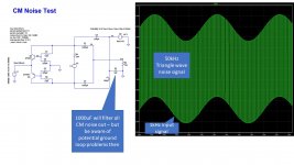
A quick sim shows that any common mode noise on the supply rails (i.e. the collectors of the transistors) feeds directly into the output*. If you connect the LED + or - to the Duraglit 0V with a large capacitor (1000uF for example) you can remove the noise, but of course you trade that for 50Hz ground loop problems so you would have to manage the wiring very carefully.
The powered version is looking more attractive by the minute to my view.
* I used a 10V pk~pk 50 kHz triangular waveform and fed it to each transistor collector with a 100 pF capacitor. Source impedance of the noise generator was 10 Ohms.
The powered version is looking more attractive by the minute to my view.
* I used a 10V pk~pk 50 kHz triangular waveform and fed it to each transistor collector with a 100 pF capacitor. Source impedance of the noise generator was 10 Ohms.
Attachments
Last edited:
For professional equipment (like broadcasting microphones or turntables) I suspect some strict rules for wiring and grounding apply. These rules may make integration of a Duraglit floating type of head amp possible, an optimal universal recipe may exist.
But for the garden variety of home audio equipment (and ways to power them from mains) I believe this is rather impossible. It is very likely the end results would we wildly variable, depending on the existing setup. I can't even imagine somebody selling such head amps and then having to support them (hear Bonsai?), I suspect the number of returns would be rather large...
But for the garden variety of home audio equipment (and ways to power them from mains) I believe this is rather impossible. It is very likely the end results would we wildly variable, depending on the existing setup. I can't even imagine somebody selling such head amps and then having to support them (hear Bonsai?), I suspect the number of returns would be rather large...
After looking closer (I will be back with a throughout analysis) I'm afraid that in the general case connecting these floating ground schematics to the outside world is more complicated than it appears at the first sight. An ideal connection would require an isolated op amp, with the input section fed from the head amp floating supply and the output side from the next stage, ground referred, power supply. Reason is, connecting the Duraglit to the outside world makes implicit conversion from balanced to single ended (ground referred). So any "common mode" noise or hum (like the one you indicated, by capacitively coupling the mains) translates to single ended hum, that eventually gets amplified...
I could build such an isolating op amp using a feedback linearized optocoupler, but the big issue is accessing the destination power supply. Which leads to the idea to optically couple the head amp to the next stage, which would not be a huge issue to do (given the signal levels at the head amp output).
But then the complexity of the whole setup would grow exponentially, and for what? For avoiding adding an input cap to isolate the cartridge, or for avoiding using jfet(s) in the input stage. Doesn't make much sense...
So this sad conclusion makes the whole floating Duraglit concept more of an academic interest. It is an interesting minimalistic concept/exercise, but I'm afraid it is not ideal for integrating, from a system perspective.
I think you have to just go with the battery - you cannot avoid the CM noise issue or potentially a ground loop issue if you decide to couple the LED supply to the Duraglit ground.
Anyway, a very interesting learning exercise.
Andreas,The floating power supply + and - rail settle themselfes approx. to +/- Vc/2 refrerenced to ground. The amplified input signal is 'riding' as a common mode signal on these lines which get converted to a single ended ground referenced signal by the output resistor. Making the power supply distributed/physical large, the chance to catch up interfering noise signals from the environment is dramatically increased. Any such interference leading to a common mode signal on the DC rails will create noise in the output - and DC regulators, when floating, can only filter and suppress differential noise signals on the input rails
On top yes, the wall-wart is isolated but only to a certain degree. There are always stray capacitances making some (high impedance) connection between primary and secondary. E.g., 100pF at 50 Hz are a 25 MOhm impedance and at 250V mains voltage, there are 10µA of 50Hz hum current flowing through your MC Headamp. Yes this is an unwanted loop but not an ordinary ground loop.
Therefore floating supplies should be small and if powered from mains should be extremely well decoupled and isolated DC and AC wise for differential and common mode noise. If you want to power from mains, an ordinary ground referenced dual supply may be the better choice because (low frequency) common mode signals are no longer playing a role and all differential noise signals can be filtered with well known filters and active regulators.
I still don't get how 60Hz Common Mode pollution on a PS, just and only feeding a number of LED's through a LM7815 followed by a LM317 current limiter, can cause a 60Hz hum on the Duraglit.
Sometimes one picture can tell more than a thousand words, so if it's not too much trouble could you enlighten your explanation with an image ?
Hans
@syn08, luckily I used a single ended JFET input stage (very similar to the 'Galileo'). Not as quiet at the Duraglit's but still very acceptable with a Hana ML (Rgen = 8 Ohms). Its not suitable for 3 Ohm ML carts, but the people who buy and use these things will usually have no compunction in shelling out a grand for an SUT in that case anyway.
Last edited:
OK being super dense here, but surely if the next phase had a differential input (I may have mentioned I like balanced+differential inputs on my stuff) then you should avoid the problem?
I've got a large USB battery pack that I use for phono power duties. That may be a better option to drive the LEDs as only connected back when charging. I understand why some don't like battery power, but takes one worry out the project for me, esp with Jan's silentswitcher for when +/-15v rails are needed.
I've got a large USB battery pack that I use for phono power duties. That may be a better option to drive the LEDs as only connected back when charging. I understand why some don't like battery power, but takes one worry out the project for me, esp with Jan's silentswitcher for when +/-15v rails are needed.
Hans, see the sim in #1209
No, that’s not what I’m asking.
That an additional CM on the Duraglit supply causes trouble is clear.
My question however is how this CM signal could land on the supply voltage.
Hans
For the heck of it, I tried a RCore transformer. No improvement in the measured hum compared to a standard analog wall wart power supply.
Not sure if a differential input (brute force, two as much as possible "identical" channels, within tolerances) will have enough CMMR to significantly improve the hum.
Once again, it's perfectly fine in my system (since I went a far way in caring about ground loops, wiring, and grounding in general); on the bench, there's one order of magnitude larger hum when feeding from the same analog power supply wall wart vs. feeding from my Agilent 6627A low noise power supply.
No, that’s not what I’m asking.
That an additional CM on the Duraglit supply causes trouble is clear.
My question however is how this CM signal could land on the supply voltage.
Hans
The whole Duraglit supply is being dragged up an down by the common mode voltage that is arising between the mains 0V and the circuit. Te wall-wart switching mosfet drain is swinging probably to 500 or 600 Volts peak wrt ground and its capacitively coupled through the transformer to the secondary side. The result will be some Volts of HF noise with 100/120 Hz ripple superimposed on it. In the sim I used 100pF to each side of the solar cell, but even with just 10pF to each side, 10V pk-pk common mode noise still gives you 3-5 mV of noise at Vout. You can connect the LED supply + or - directly to the Duraglit ground and it blocks the CM noise problem, but you then have ground loops to worry about.
So, it seems the operating requirements
1. maintain very low non-signal related CM noise across the battery (solar cell)
2. keep any extraneous capacitive coupled noise to the transistor collectors to a minimum (low single digit pF)
3. keep the power supply and the circuit compact and of course shield it (same comment as Andreas made)
4. absolutely make sure there is no common mode noise between the amplifier ground and the floating power supply
(NB - One option to try might be a suitable ferrite CM clamp core around wire from the wall-wart to the LED's)
Last edited:
OK being super dense here, but surely if the next phase had a differential input (I may have mentioned I like balanced+differential inputs on my stuff) then you should avoid the problem?
I've got a large USB battery pack that I use for phono power duties. That may be a better option to drive the LEDs as only connected back when charging. I understand why some don't like battery power, but takes one worry out the project for me, esp with Jan's silentswitcher for when +/-15v rails are needed.
I think the battery pack will be a step in the right direction because it is 'more floating' wrt the Duraglit circuitry than a power source that is derived from an SMPSU that's plugged into the mains.
The battery powered Duraglit has 0 dB PSRR.
Not sure if a differential input (brute force, two as much as possible "identical" channels, within tolerances) will have enough CMMR to significantly improve the hum.
At the levels we are talking about it's challenging. Once at line level of course the THAT1200 series Could always use your Nemesis... an output transformer.
- Home
- Source & Line
- Analogue Source
- Richard Lee's Ultra low Noise MC Head Amp