Bonsai,Hans, on the Hawking, if you run your sims but look at the collector voltage of the transistors before the DC blocking caps (with or without dampers) what are you getting? This is with the 10uF capacitors
Is this what you mean, collector voltages are V(V+) and V(V-), lying exactly on top of each other.
Two Sims, one for Rs=5R gain=10 and one for Rs=1R gain=50, both with output cap 10uF, no damping.
Hans
Attachments
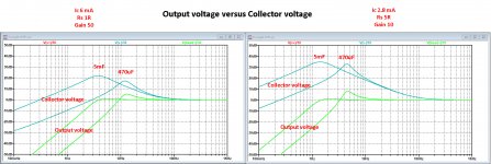
Are you not losing head room because the voltage on the collector before the output coupling cap is peaking at LF?
Looking at this situation, my feeling is the base decoupling caps can stay at 220uF, but the output coupling caps should be large - say 1000uF. This way you lose no headroom and you get no peaking about say 1 or 2 Hz where it is so small anyway that it is insignificant.
If the collector load (the output cap Xc + the total output load resistance including damper or no damper + the 100 Ohm to ground) increases, the gain will increase and you will get some kind of peaking. The solution therefore it seems is to keep Xc flat to << 1~2 Hz.
Just my thoughts.
")
Looking at this situation, my feeling is the base decoupling caps can stay at 220uF, but the output coupling caps should be large - say 1000uF. This way you lose no headroom and you get no peaking about say 1 or 2 Hz where it is so small anyway that it is insignificant.
If the collector load (the output cap Xc + the total output load resistance including damper or no damper + the 100 Ohm to ground) increases, the gain will increase and you will get some kind of peaking. The solution therefore it seems is to keep Xc flat to << 1~2 Hz.
Just my thoughts.
Last edited:
Bonsai,Are you not losing head room because the voltage on the collector before the output coupling cap is peaking at LF?
Looking at this situation, my feeling is the base decoupling caps can stay at 220uF, but the output coupling caps should be large - say 1000uF. This way you lose no headroom and you get no peaking about say 1 or 2 Hz where it is so small anyway that it is insignificant.
If the collector load (the output cap Xc + the total output load resistance including damper or no damper + the 100 Ohm to ground) increases, the gain will increase and you will get some kind of peaking. The solution therefore it seems is to keep Xc flat to << 1~2 Hz.
Just my thoughts.
Good question about headroom, let's do a worst case calculation, which is for a 0.5mV 5R Cart, see image in #741.
1) Vmax for the collector voltages of the Duraglit is ca. 500mV rms.
2) Looking at the image in #741, collector voltage at 10Hz is 20dB above output voltage, so Vmax rms out @ 10Hz is 50mV.
3) With Riaa premphasis 0.5mV@5cm/sec@Khz drops to ca. 0.05mV@10Hz.
4) A 0.5mV Cart needs a Headamp gain of 20dB to be compatible with the MM input.
5) So Vin@0.05mV@10Hz gives a Vout of 0.5mV with this gain of 20dB
(Vout max)/(Vout@0dB@10Hz) = 50mV/0.5mV resulting in 40dB overload margin.
Where 30dB is regarded to be very good, 40dB is more than excellent and nothing to worry about.
Using 5mF + 10uF will give just one single Caps solution that fits all applications independent of Gain and Rs, whereas using 200uF or even larger output caps with a damping resistor will remove headroom over the complete FR and needs adjustment for each individual Cart / gain combination.
That's why to my opininion the 5mF +10uF solution seems to be the clear winner.
Hans
What would one recommend for a 5mF cap?
What about 2x 2.7mF 2.5Volt Oscon Alu Polymer ?
Hans
What about 2x 2.7mF 2.5Volt Oscon Alu Polymer ?
Or those mentioned here https://www.diyaudio.com/forums/ana...tra-low-noise-mc-head-amp-71.html#post5856279
Absolutely no noise contribution, to my measurements.
What about 2x 2.7mF 2.5Volt Oscon Alu Polymer ?
Or those mentioned here https://www.diyaudio.com/forums/ana...tra-low-noise-mc-head-amp-71.html#post5856279
Absolutely no noise contribution, to my measurements.
- Does this mean the Nichicon 2V5 high value 'CAP ALUM POLY's vary from value to value or perhaps individually? syn08 appears to have had good results while Gerhad did not.
- Are we also saying wet slug Tantalums (whatever they are) don't have this EVIL 1/f & greater noise?
- My 2c is that in the 80s, cheapo Aluminium electrolytics worked well especially the Panasonic Lo Leakage ones.
- Also Jurassic caps with slightly higher voltage rating had a paper ESR rather less than the very low voltage ones and this was borne out by simple listening tests in a test jig. My original document specified 25V caps because of this. I'm not sure if this holds in da 21st century.
- I think my recommendation to actually listen to the noise of the base capacitors is still valid for those wishing the very best performance. But surely with all the expertise here, we can now point to something in the datasheets that tells us what to look for? aboos has suggested low leakage for Aluminium electrolytics. Is this enough to discard the EVIL organics & polymers? It obviously doesn't hold for Tantalums but we know to avoid these.
Last edited:
Bonsai, I think Hans' solution is the correct one for Duraglit.Are you not losing head room because the voltage on the collector before the output coupling cap is peaking at LF?
Looking at this situation, my feeling is the base decoupling caps can stay at 220uF, but the output coupling caps should be large - say 1000uF. This way you lose no headroom and you get no peaking about say 1 or 2 Hz where it is so small anyway that it is insignificant.
If the collector load (the output cap Xc + the total output load resistance including damper or no damper + the 100 Ohm to ground) increases, the gain will increase and you will get some kind of peaking. The solution therefore it seems is to keep Xc flat to << 1~2 Hz.
I note my original Wireless World 1981 article specified 22u output capacitors and I'm going to claim I investigated all this fully then
then forgot all about it Thank you Guru Hans for your fine work
A more formal version of Hans' 'worse case calculation' would be to look at Tomlinson's data which he originally presented in Audio magazine. I'm not sure which of his AES papers has the data which I think is still definitive for recorded levels and also what to expect from warps. Wayne found the original Audio article some years ago and I think its archived on his proaudiodesign.com website.
It will show that Hans is right and the use of 10u output capacitors will not be anywhere near overload at LF while damping resistors will be sailing close to the wind at mid frequencies & higher at times.
BTW, the Wireless World article also shows the onset of 'overload' starting above 100mV for a 3R cartridge and a 1v5 battery. It's quite 'gradual' and very different from the clipping of most other circuits. The 6R cartridge has overload starting above 150mV. Below these levels, THD is almost all due to the input stage.
Running higher currents gives less THD.
The issue is not overload - it’s that you have to keep the output load constant right down to very low frequencies. If it increases, you get peaking and loss of head room and it’s especially an issue at the frequencies between 2 and say 10 Hz where arm resonance is of concern.
Anyway, seems Hans has got a good solution - I will have to play with it a bit to understand his approach better.
Anyway, seems Hans has got a good solution - I will have to play with it a bit to understand his approach better.
Agreed.The issue is not overload - it’s that you have to keep the output load constant right down to very low frequencies. If it increases, you get peaking and loss of head room and it’s especially an issue at the frequencies between 2 and say 10 Hz where arm resonance is of concern.
Thanks for your positive reaction.Anyway, seems Hans has got a good solution - I will have to play with it a bit to understand his approach better.
I will have another look at the Holman's papers.
Hans
Excuse me if I belabour this point but I feel it is the last unknown obstacle to a DIYer making a battery powered Duraglit MC head amp with true SOTA noise.
- Does this mean the Nichicon 2V5 high value 'CAP ALUM POLY's vary from value to value or perhaps individually? syn08 appears to have had good results while Gerhad did not.
- Are we also saying wet slug Tantalums (whatever they are) don't have this EVIL 1/f & greater noise?
- My 2c is that in the 80s, cheapo Aluminium electrolytics worked well especially the Panasonic Lo Leakage ones.
- Also Jurassic caps with slightly higher voltage rating had a paper ESR rather less than the very low voltage ones and this was borne out by simple listening tests in a test jig. My original document specified 25V caps because of this. I'm not sure if this holds in da 21st century.
- I think my recommendation to actually listen to the noise of the base capacitors is still valid for those wishing the very best performance. But surely with all the expertise here, we can now point to something in the datasheets that tells us what to look for? aboos has suggested low leakage for Aluminium electrolytics. Is this enough to discard the EVIL organics & polymers? It obviously doesn't hold for Tantalums but we know to avoid these.
Leakage current in electrolytics is a complex topic and not straightforward. Here is what I extracted from various papers and application notes from manufacturers as well as from some own experience in the past:
Leakage currents in electrolytics can have two major sources:
- leakage through defects in the oxide layer and
- leakages as ohmic bypasses between the leads inside the cap (but not through the oxide layer).
While the first one may produces high noise the latter one is more resistor like and is usually so mall that we can ignore it.
Leakage through layer defects is highly variable and depends on base materials, production technologies, elecrtolytes used and storage/ageing without applied voltage. This storage effect is based on chemical processes that weaken the oxide layer and create defects. These defects get mostly repaired as soon as the caps get biased. That's the reason why manufacturers specify the leakage current after two to five minutes time of operation and why the normally observe leakages are much lower an reality (time is money and nobody is willing to wait for an hour to measure the final remaining leakage).
Today this storage effect is much lower than it has been 40 years ago - but is still relevant (remember the general advise to 'reformat' caps before use if they were not new. This was especially recommended for high voltage types to avoid overheating when powered up the first time)
In summary, all these effects could explain why some have seen no noise issue with caps while others have reported substantial noise with very similar caps.
Bottom line, measuring and listening with the final circuit may be the only way to find caps with acceptable noise performance.
An interesting experiment could be as someone has noise issues with a certain cap to simply bias it with the normal working voltage for let's say one hour and remeasure the noise again.
< https://www.google.de/url?sa=t&rct=...2/746790.pdf&usg=AOvVaw0kox_dHnNB4uhaRoIizrtT >
seems interesting, but not yet worked through.
Jim William's App note 124:
< http://www.dwintech.com/an124-LinearTech_LSK389_P3.pdf >
This file has some annotation in red from someone else, but harmless.
The version you get now from AD has some parts missing.
Appendix B is on wet tantalums.
< https://www.analog.com/media/en/tec...rticle/LTMag-V19N4-02-LTC6655-JimWilliams.pdf >
AVX is 3 dB cheaper than Vishay.
I bought just ONE to see if it really makes a difference.
JW's type goes to 200°C, mine doesn't.
Since leakage is linked to high temperature performance, I decided on
DigiKey 493-4495-1-nd or P15342ct-nd as a cheap compromise, still untested.
ed. this P15... thing now seems to be something completely different
than what I have bought on June-4.
Gerhard
Last edited:
Very interesting article !
It just describes the noise modes and dependencies on storage, temperature etc I mentioned in my previous post also for tantalums - same mechanisms as for aluminium electrolytics.
I also came to the almost same conclusion as you to test the Panasonic FR type for their (hopefully very low) noise behaviour.
They have low leakage combined with very low ESR (for he caps in physically larger casings) and withstand high temperatures. The datasheet also describes the leakage current behaviour after prolonged storage at 105degC. After 'voltage treatment' (which is responsible to repair the oxide layer defects) it is claimed that leakage current is still within initial specifications.
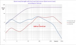
The image below shows the result of copying into Excel the Holman Worst Case Envelope after Riaa (blue) and the corrected pre Riaa curve (Red) for a 5R 0.5mV Cart in combination with a Duraglit set to a gain of 20dB.
At 1kHz and above, V(out-max) for the Duraglit is 500mV eff.
When using the before mentioned 5mF+10uF combination, Collector voltages at LF will be higher as the output voltages, forcing V(out-max) to be quite a bit lower, see image in #741.
Together with both Holman related curves, Duraglit's V(out-max) is now shown in the image in purple.
As can be seen, the purple curve lies way above the maximum pre Riaa Holman envelope in red.
There is absolutely no danger for clipping or overloading.
I have taken this 5R 0.5mV Cart at a gain of 20dB, because here the worst conditions are met in the LF reduction of the output voltage.
Even a 1R 0.1mV Cart with Gain 50 running at a collector current of 6 or 12mA, will be less demanding.
Hans
Attachments
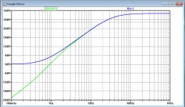
When setting the base capacitors to 100µF and the output capacitors to 470µF or bigger, there will be no gain increase at verx low frequencies nor will be there a headroom decrease as the collector voltages are not higher than the output anymore. Thus the 500 mV max signal level for Duraglit will be maintained over the entire frequency range.
And this values are an almost 'one size fits all' as this behaviour remains almost unchabnged over a wide Rs input range and over a wide gain range.
View attachment Hawking_AB Gain curves.pdf
View attachment Hawking_AB.pdf
And this values are an almost 'one size fits all' as this behaviour remains almost unchabnged over a wide Rs input range and over a wide gain range.
View attachment Hawking_AB Gain curves.pdf
View attachment Hawking_AB.pdf
When setting the base capacitors to 100µF and the output capacitors to 470µF or bigger, there will be no gain increase at verx low frequencies nor will be there a headroom decrease as the collector voltages are not higher than the output anymore. Thus the 500 mV max signal level for Duraglit will be maintained over the entire frequency range.
And this values are an almost 'one size fits all' as this behaviour remains almost unchabnged over a wide Rs input range and over a wide gain range.
View attachment 770309
View attachment 770310
For a gain of 20dB with a 5R cart or larger, you are right.
But look what happens when using a 1R 0.1mV Cart needing a gain of 50.
At 20Hz, FR is -6dB down, unacceptable and out of the question.
So this seems not to be the "one size fits all" solution like the 5mF+10uF.
Hans
P.S. This is for Ic=12ma. When using Ic=6mA FR is -3dB@20Hz and largely dependent on the Hfe of the transistors.
Attachments
Last edited:
- Home
- Source & Line
- Analogue Source
- Richard Lee's Ultra low Noise MC Head Amp