My HH simulation includes power supply noise.
A 60 Ohm resistor delivers 1 nV/rtHz. it is multiplied as needed with a VCVS.
That is added to the clean power supply. A microvolt offset or so is needed
to prevent LTspice from crashing. That is dwarfed by the clean supply.
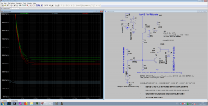
You can plot the influence of the PS noise with the expression onoise(R60Ohm)/gain
in the usual way. It is demonstrated in the HH amplifier for 2 nV/rt Hz. That's what
an LT3042 / 3045 can deliver. Still OK.
Now I'll drive 1000 Km home to flee from the 42°C that are announced.
Won't help much.
A 60 Ohm resistor delivers 1 nV/rtHz. it is multiplied as needed with a VCVS.
That is added to the clean power supply. A microvolt offset or so is needed
to prevent LTspice from crashing. That is dwarfed by the clean supply.
You can plot the influence of the PS noise with the expression onoise(R60Ohm)/gain
in the usual way. It is demonstrated in the HH amplifier for 2 nV/rt Hz. That's what
an LT3042 / 3045 can deliver. Still OK.
Now I'll drive 1000 Km home to flee from the 42°C that are announced.
Won't help much.
No, a 6 dB transistor penalty.
I just quoted H&H’s number Gerard. It if they are wrong, thanks for pointing it out.
Now I'll drive 1000 Km home to flee from the 42°C that are announced.
Won't help much.
Erk. I was in Italy 2 weeks ago and 32°C was more than enough (actually too much for the little ones). Glad I selected the week I did. Hope the tarmac doesn't melt.
And for our American cousins, yes I know Texas regularly gets weeks on end of 40+ degree heat. Still doesn't make it nice to endure!
I can't remember where to find this, but John Curls comment was that this makes the sound a bit muddy.
John has usually attributed that to driving a MC cart into a virtual ground. Remember there is a large group of listeners that insist on picking a load R and using a relatively high impedance pre-pre-amp.
For several reasons I still believe the JC-80 was a great compromise for almost all MC users at 0.4nV. I hope this can be included even though the FET's are probably the most unavailable of all.
My HH simulation includes power supply noise.
A 60 Ohm resistor delivers 1 nV/rtHz.
Gerhard how did you insert your 60 Ohm cal noise into the 20 op-amp circuit? The Ib noise would seem to add at least some error, small, and maybe I just missed it.
I've done this for a number of circuits. My exercise with Leach was built, measured and was/is used in a number of real life MC vinyl playback systems from circa 1980Oh, incidentally, before claiming to be able to "throw bits out & get better performance", perhaps it is advisable to build in real life first .....
In real life, that is, not in Spice.
I don't usually post stuff I haven't tried or persuaded someone to try. But I was so impressed by Hans' work on MM cartridges that I thought I should help him out with his hero, JC. That one hasn't been built this Millenium but I might have tried it circa 1980. If I did, there must be some reason why I rejected it so I'm eager that someone builds, measures and tries it in a real life MC vinyl playback system ... compared directly with mine of course
I'll pass on other circuits where I've thrown bits out & got better performance as I'm conscious I'm already waving rude bits around
The reason I throw bits out is cos my small brain has difficulty understanding stuff with loadsa bits Yes. For this, the Leach topology is a lot better than JC's or anything with grounded PS. ... which is why I still recommend my Duraglit battery special.syn08 said:To my experience, power supply noise injection is the largest contributor to excess noise (on top of what an accurate simulation of the signal path predicts).
I see I've already linked to your page in my 'original' document and you have at least one new design with improved performance since I looked many years ago. ZTX851/951 allows me to move ahead again slightly but of course you could use them toosyn08 said:Sure, I did one at the about the same noise or slightly better, about 10 years ago, see attached. Left channel is 0.26nV/rtHz, right channel 0.29nV/rtHz. Could be much lower, but I wanted it for high input impedance (at that time I had a 2mV high output MC cartridge which was optimized for 47k input impedance), so some trade off was unavoidable (input stage is emitter follower with no gain, but it adds to the input referred noise another Rbb). The input current noise was about 3.7pA/rtHz, so it is good up to 40-50ohm source impedance without impacting the overall noise. Rohm 2SD786/2SB737 transistors.
Your circuit is certainly more versatile cos less current noise reduces the need for matching. And it is full RIAA. Conversely, your circuit is slightly more complicated than mine
and I dare not suggest throwing bits out ...
Last edited:
I see I've already linked to your page in my 'original' document and you have at least one new design with improved performance since I looked many years ago.
You probably missed this one, no more power supply noise issues, can be fed from your favorite battery, though. Even a pair of LM317/LM337 are good enough. A LM317/LM337 power supply version with JFETs running at Idss has 0.33nV/rtHz and is posted here.
Thanks for this syn08 but it's only 450pV/rt(Hz)You probably missed this one, no more power supply noise issues, can be fed from your favorite battery, though.
The temptation to suggest throwing things out to get more performance on HTP4.1 is becoming nearly overwhelming ... Just shut up Lee! Just SHUT UP !!!
Thanks for this syn08 but it's only 450pV/rt(Hz)
The temptation to suggest throwing things out to get more performance on HTP4.1 is becoming nearly overwhelming ... Just shut up Lee! Just SHUT UP !!!
I'll look around for the 10 years old noise results of 64 BF862 in parallel, under 0.2nV/rtHz and a rock solid feedback loop. Although I doubt you are interested, cobbling together two ZTX transistors is so much more rewarding, isn't it
?Otherwise, good idea. Your "beach bum" language is indeed overwhelming, tiresome, and I don't find it at all funny.
Bonsai started this thread as a service to the community at large we should keep it civil. Richard, optimization along one dimension has its appeal and limitations and at some point it simply becomes reductionist. Considering the application making noise the only parameter that matters at all costs is not productive. As I said there are a lot of users that will never consider a virtual ground (low impedance) input or a large quantity of big capacitors in the signal path. Let's let the variety of solutions flourish.
As I said there are a lot of users that will never consider a virtual ground (low impedance) input
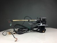
Part of me is jealous that they can cut out such options so easily. After all this can on the bottom of the tonearm is almost crying out to have a simple gain stage fitted.
Attachments
I think all of us have learnt something from this thread. Some crazy has even improved JC's noise by 4.4dB, his THD by 3dB AND simplified his circuitBonsai started this thread as a service to the community at large we should keep it civil. Richard, optimization along one dimension has its appeal and limitations and at some point it simply becomes reductionist. Considering the application making noise the only parameter that matters at all costs is not productive. As I said there are a lot of users that will never consider a virtual ground (low impedance) input or a large quantity of big capacitors in the signal path. Let's let the variety of solutions flourish.
So these changes are certainly not just reductionist & one dimensional.I would have thought this sort of thing are the real gems in DIY forums. But from Guru Wurcer and other people's reactions to simplification and improvement, I have consciously refrained from simplifying & improving syn08 & EUVL's in case I invoke their wrath.
BTW, I'm certain Guru Wurcer sees the obvious simplifications & improvements in syn08's circuit but you guys will have to persuade him to speak up.
If a zillion devices & complexity rocks your boat, that's OK as this is DIY. But if your aim is SOTA noise (cue 3 pages of rant from Wurcer about noise >20dB below record bla bla), you might like to spend an hour knocking up my circuit while you try to emulate its real life performance with something more complex.
Syn08's article has loadsa useful stuff if you want to build SOTA noise stuff. But I'm certain the typical DIYer will have problems approaching his results even with his PCBs etc. My slightly simpler amp has a slightly better chance of the DIYer getting the SPICE world SOTA results in a real life MC vinyl playback system.
As for "virtual ground (low impedance) input or a large quantity of big capacitors in the signal path", my 2c on EVIL caps is in my doc.
But did JC disown later disown the wonky virtual earth that Hans posted?
JC has disowned his own stuff on a number of occasions.
Last edited:
I just quoted H&H’s number Gerard. It if they are wrong, thanks for pointing it out.
No, there is nothing wrong; you need twice the number of transistors to go from single ended to differential and then double that again to make up for the 2 BE junctions in series, so 4 times the number of transistors all in all. Win Hill is a regular in the usenet group sci.electronics.design and we have discussed my amputated version of his amplifier there shortly. We still are friends.
google groups is a clumsy back door to s.e.d.
Scott: The 60 Ohm cal resistor at the input still works quite OK for the 10*2*ADA4898. It still delivers the expected voltage noise levels. Maybe the the 4898 is even better so it can afford the slight handicap.
For the H&H amplifier, one definitely cannot ignore the noise current. I think I used ~0R6 there. It should be visible in the simulation if set up so.
snip here, put this in a file and call it 16xZTX851.asc and use it with LTspice: (May need a larger Rbb or so to conform better to reality)
green: all in all performance
red: noise of transistors
grey: contribution of VCC noise.
m=16 means 16 of these thingies in parallel.
%<-----%<-----%<-----%<-----%<-----%<-----%<-----%<-----%<-----%<-----
Code:
Version 4
SHEET 1 2048 1328
WIRE -240 -1136 -320 -1136
WIRE -240 -1120 -240 -1136
WIRE -48 -1104 -192 -1104
WIRE 176 -1104 -48 -1104
WIRE 224 -1104 176 -1104
WIRE 336 -1104 224 -1104
WIRE -192 -1072 -192 -1104
WIRE -240 -1056 -240 -1120
WIRE -368 -1024 -384 -1024
WIRE -320 -1024 -320 -1056
WIRE -320 -1024 -368 -1024
WIRE 176 -1024 176 -1104
WIRE -320 -1008 -320 -1024
WIRE -192 -944 -192 -992
WIRE -288 -928 -320 -928
WIRE -240 -928 -240 -1008
WIRE -240 -928 -288 -928
WIRE -192 -928 -192 -944
WIRE -48 -928 -48 -1104
WIRE -288 -912 -288 -928
WIRE 48 -880 16 -880
WIRE 96 -880 48 -880
WIRE 176 -880 176 -944
WIRE 48 -848 48 -880
WIRE -48 -752 -48 -832
WIRE 176 -656 176 -880
WIRE 256 -656 176 -656
WIRE 320 -656 256 -656
WIRE 176 -624 176 -656
WIRE 352 -576 240 -576
WIRE 352 -560 352 -576
WIRE 176 -496 176 -528
WIRE 176 -464 176 -496
WIRE -224 -416 -288 -416
WIRE -208 -416 -224 -416
WIRE -48 -416 -48 -672
WIRE -48 -416 -144 -416
WIRE 112 -416 -48 -416
WIRE -288 -352 -288 -416
WIRE -48 -352 -48 -416
WIRE 176 -272 176 -368
WIRE -288 -208 -288 -272
WIRE -288 -176 -288 -208
WIRE -288 -64 -288 -96
FLAG -192 -848 0
FLAG -288 -64 0
FLAG 224 -1104 vcc
FLAG -288 -208 vgen
FLAG -288 -912 0
FLAG -368 -1024 v3p
FLAG -240 -1120 v3r
FLAG -192 -944 v1p
FLAG -48 -272 0
FLAG 48 -784 0
FLAG 256 -656 raus
FLAG 352 -480 0
FLAG 176 -496 c1
FLAG 176 -272 0
FLAG -288 -576 0
FLAG -224 -416 rein
SYMBOL voltage -192 -944 R0
WINDOW 0 -32 56 VBottom 2
WINDOW 3 32 56 VTop 2
WINDOW 123 0 0 Left 2
WINDOW 39 -52 151 VTop 2
SYMATTR InstName V1
SYMATTR Value 7
SYMATTR SpiceLine Rser=0.001
SYMBOL voltage -288 -192 R0
WINDOW 123 24 160 Left 2
WINDOW 39 24 132 Left 2
WINDOW 3 -155 185 Left 2
SYMATTR Value2 AC 1
SYMATTR SpiceLine Rser=0
SYMATTR Value SINE(0.0 0.001 2000000 0 0 0)
SYMATTR InstName V2
SYMBOL cap -144 -432 R90
WINDOW 0 0 32 VBottom 2
WINDOW 3 32 32 VTop 2
SYMATTR InstName C2
SYMATTR Value 10000
SYMATTR SpiceLine Rser=1m
SYMBOL e -192 -1088 R0
SYMATTR InstName E1
SYMATTR Value 2
SYMBOL res -336 -1152 R0
SYMATTR InstName R1
SYMATTR Value 60
SYMBOL voltage -320 -1024 R0
WINDOW 0 -32 56 VBottom 2
WINDOW 3 32 56 VTop 2
WINDOW 123 0 0 Left 2
WINDOW 39 -57 138 VTop 2
SYMATTR InstName V3
SYMATTR Value 0.1
SYMATTR SpiceLine Rser=0.1
SYMBOL res -64 -368 R0
SYMATTR InstName R2
SYMATTR Value 2k2
SYMBOL res -64 -768 R0
SYMATTR InstName R3
SYMATTR Value 2k2
SYMBOL res 192 -896 R90
WINDOW 0 0 56 VBottom 2
WINDOW 3 32 56 VTop 2
SYMATTR InstName R4
SYMATTR Value 22k
SYMBOL cap 32 -848 R0
SYMATTR InstName C3
SYMATTR Value 100
SYMBOL npn 16 -928 M0
WINDOW 0 -8 -39 Left 2
WINDOW 3 -55 -11 Left 2
SYMATTR InstName Q3
SYMATTR Value ZTX851
SYMBOL res 160 -1040 R0
WINDOW 123 37 107 Left 2
SYMATTR Value2 m=3
SYMATTR InstName R5
SYMATTR Value 51
SYMBOL npn 112 -464 R0
WINDOW 0 91 30 Left 2
WINDOW 3 89 86 Left 2
WINDOW 123 91 58 Left 2
SYMATTR InstName Q4
SYMATTR Value ZTX851
SYMATTR Value2 m=16
SYMBOL npn 240 -624 M0
WINDOW 0 91 30 Left 2
WINDOW 3 89 86 Left 2
WINDOW 123 91 58 Left 2
SYMATTR InstName Q1
SYMATTR Value ZTX851
SYMATTR Value2 m=1
SYMBOL voltage 352 -576 R0
WINDOW 0 -32 56 VBottom 2
WINDOW 3 32 56 VTop 2
WINDOW 123 0 0 Left 2
WINDOW 39 -52 151 VTop 2
SYMATTR InstName V4
SYMATTR Value 2.9
SYMATTR SpiceLine Rser=0.001
SYMBOL res -304 -592 R0
SYMATTR InstName R6
SYMATTR Value 0.05
SYMBOL res -304 -368 R0
SYMATTR InstName R7
SYMATTR Value 1m
TEXT 272 -840 Left 2 !;tran 0 2m 1.97m
TEXT -104 -1128 Left 2 ;Vcc + E1 * 1n VRtHz noise
TEXT 272 -864 Left 2 !.op
TEXT 272 -808 Left 2 !.noise v(raus) V2 dec 1000 1 10e6
TEXT 272 -784 Left 2 !;ac dec 1000 10 10Meg
TEXT 264 -728 Left 2 !.temp 20 40 60
TEXT -344 -208 VLeft 2 ;50/0.005 Ohm = - 60 dB attenuator
TEXT 432 -256 VLeft 2 ;BZX84C2v7  + cap + Res to Vcc
TEXT -128 -216 Left 2 ;Q1 is really one 2SC3420 because avail. but model missing.
TEXT -96 -168 Left 2 !*ZETEX  ZTX851 Spice model   Last revision 21/1/93  (C)  1993 ZETEX PLC \n* 200 pV/rtHz according to AOE3\n \n \n.MODEL ZTX851 NPN IS =1.0085E-12 NF =1.0001 BF =240 IKF=5.1 VAF=158\n \n+             ISE=2E-13 NE =1.38 NR =0.9988 BR =110 IKR=5.5 VAR=46 \n \n+             ISC=4.6515E-13 NC =1.334 RB =0.025 RE =0.018 RC =0.015 \n \n+             CJC=155E-12 MJC=0.4348 VJC=0.6477 CJE=1.05E-9 \n \n+             TF =0.79E-9 TR =24E-9
Attachments
Last edited:
 @gerhard - you can just attach the asc file.
usenet group sci.electronics.design
< Google Groups >
Google have just collected the contents and present it now as a google group.
Awful signal/noise, but still some bright people there.
The group predates the www.
< Google Groups >
Google have just collected the contents and present it now as a google group.
Awful signal/noise, but still some bright people there.
The group predates the www.
Gerhard,Scott: The 60 Ohm cal resistor at the input still works quite OK for the 10*2*ADA4898. It still delivers the expected voltage noise levels. Maybe the the 4898 is even better so it can afford the slight handicap.
Very elegant way to add calibrated noise to a line as you did with the 60R resistor and a VDVS.
Thanks for the idea.
Hans
I find it a bit hard to believe of the hundreds of thousands MC users, even 1% ever auditioned a virtual ground input, I haven't.As I said there are a lot of users that will never consider a virtual ground (low impedance) input or a large quantity of big capacitors in the signal path. Let's let the variety of solutions flourish.
But I can imagine that not the sonic but the impractical side of a virtual input, i.e. changing Rf for every different Cart used, withholds people.
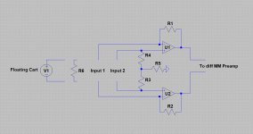
But to leave it up to the user, that's why I propagated a diff topology here
Designing a universal diff-in/diff-out Head Amp
where both a virtual input and a high impedance input could be selected with the same amp, enabling it to compare apples to apples.
Hans
Attachments
Those TPS7 TI regulators are extremely good indeed.
For very low power consumption like the Lee or JC topology, Alkaline AA batteries with 2600mAh producing 1nV/rthz or less https://tf.nist.gov/general/pdf/1133.pdf
contribute to an unmeasurable amount to the output noise and will last at least for a full year of listening.
Hans
- Home
- Source & Line
- Analogue Source
- Richard Lee's Ultra low Noise MC Head Amp