Examples of only the circuits being discussed here, or other (similar) ones as well?... May I conduct a little poll ?
We've had loadsa sims but how about real life examples, actually in use in vinyl playback systems. I've got 280pV/rt(Hz) and I think Wayne has 500pV/rt(Hz) in his balanced system .. both measured as well as simmed.
Any more real life examples?
I built and am using Leaches common-base current-mirror variant (using THAT-340 dual matched pairs, optimized to my cart: Ortofon MC20). It can't compete with the "supadupa" low-noise being discussed here, but it's MORE than low enough for my needs, works very well, and sounds great.
Happy to share more if interested.
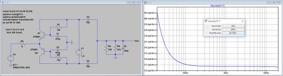
I've redone the sims for a 5R source resistance with the adjusted 1R2 and 1R5 values for the ZTX devices.No. My 1980 measurement of 0.28nV/rt(Hz) was with a 5R (IIRC) resistor.
Since the Leach-ML gain changes a bit from 34.47 to 31.77 with the 5R resistor, I also changed the JC-ML version to this exact gain.
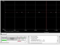
In the sim below, noise including 5R becomes 0.37nv/rtHz but unfortunately not the above mentioned 0.28nV/rtHz.
I mentioned that things are a bit more complicated and that's because the Leach topology has no connection to gnd, preventing DC current from flowing into the Cart, but with the JC topology an undefined amount of DC current may flow into the Cart.
I can't remember where to find this, but John Curls comment was that this makes the sound a bit muddy.
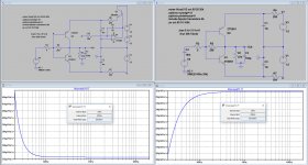
There are two ways to block this DC current, 1) an ugly 10mF cap or 2) a servo.
I don't like caps in series with an MC Cart, so my preference would be the servo, but I have simmed both. As can be seen, both produce the same 0.35nV/rtHz noise.
Hans
Attachments
I wonder why nobody had the patience to do a trivial spice exercise and identify the noise properties of the transistor model. Here's what you get in PSpice, it LTSpice provides the same, then the discrepancies are elsewhere in the schematics.
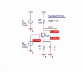
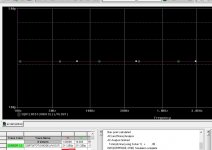
noise-schematic.jpg, schematic for the test
noise-default-model.jpg, result for ZTX851 default model @ Ic=5mA. Flat noise (as expected) 211pV/rtHz. gm=5*40=200mS, rendering a noise source of 1/(2*gm)=200pV/rtHz. 211pV/rtHz simulated vs. 200pV/rtHz quick pen and paper calculation, couldn't get closer.
noise-with-RB.jpg, result for ZTX851 with RB=1.5ohm same Ic=5mA. Same flat noise (as expected) with 263pV/rtHz. This is 4.3ohm equivalent. Now subtract the SQRT(2*q*Ib)*RB noise and the 1/(2*gm) we get the noise calculated Rbb=1.8 ohm, pretty good fit, if you ask me, with RB=1.5ohm used in the model.
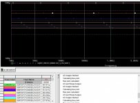
noise-with-ic.jpg, results for ZTX861 with RB=1.5ohm and variable Ic, 1mA to 7mA top-down in the table. Checking for extremes, @1mA we get a noise calculated Rbb=3ohm and @7mA we get Rbb=1.75ohm
Conclusion is that the noise equivalent Rn=RB+1/(2*gm) approximation for the noise holds only for larger collector currents. At low collector currents, this approximation is optimistic. I'll check again the bipolar model template and the default values in PSpice to understand this discrepancy at low collector currents (1mA or lower).
If anybody could repeat this in LTSpice and see if they get the same numbers...
noise-schematic.jpg, schematic for the test
noise-default-model.jpg, result for ZTX851 default model @ Ic=5mA. Flat noise (as expected) 211pV/rtHz. gm=5*40=200mS, rendering a noise source of 1/(2*gm)=200pV/rtHz. 211pV/rtHz simulated vs. 200pV/rtHz quick pen and paper calculation, couldn't get closer.
noise-with-RB.jpg, result for ZTX851 with RB=1.5ohm same Ic=5mA. Same flat noise (as expected) with 263pV/rtHz. This is 4.3ohm equivalent. Now subtract the SQRT(2*q*Ib)*RB noise and the 1/(2*gm) we get the noise calculated Rbb=1.8 ohm, pretty good fit, if you ask me, with RB=1.5ohm used in the model.
noise-with-ic.jpg, results for ZTX861 with RB=1.5ohm and variable Ic, 1mA to 7mA top-down in the table. Checking for extremes, @1mA we get a noise calculated Rbb=3ohm and @7mA we get Rbb=1.75ohm
Conclusion is that the noise equivalent Rn=RB+1/(2*gm) approximation for the noise holds only for larger collector currents. At low collector currents, this approximation is optimistic. I'll check again the bipolar model template and the default values in PSpice to understand this discrepancy at low collector currents (1mA or lower).
If anybody could repeat this in LTSpice and see if they get the same numbers...
Attachments
Maybe Hans can do that - I’m tied up until Tuesday next week with commercial activities.
I already performed the first two steps at 5mA with exactly the same results.
The 1mA to 10mA test is a good idea, tomorrow no opportunity to do it, but saturday no problem.
However we need a real world reliable measurement to validate the model.
Why 1R5 or whatever other value ?
Hans
Just to confirm RB in the 851 is 1.5 Ohms and in the 951 it’s 1.8 Ohms?
Not sure, values are pretty odd.
All things being equal (are they?) pnp RB should be lower than the npn RB. Simple fact with the n base carriers (electrons) in pnp's like the ZXT951 have a higher mobility, at the same concentration, compared with the holes in the p base for npn's like the ZXT851.
Measuring such low RB values is difficult; what I did in another life was to measure the output noise power and gain for a bunch of transistors (lots of averaging for each), at a convenient collector current (some 5mA if memory serves) with external base resistors of 2,3,4,5,6,8,10ohms.
For each resistor value, calculate the input referred noise power, average the results for at least 50 devices, calculate Gaussian dispersion and use a chi-square test to eliminate extreme results. Plot the input referred noise power vs. the external base resistor value. It should be a straight line and its extrapolated X axis intercept is the intrinsic RB value. This value includes a bunch of intrinsic resistive contributions, starting with the wire bond, wire bond to metallization, metallization, metal semi contact, diffusion geometry, etc... some of which could be slightly non linear at those levels, hence it is almost impossible to separate their contribution for further process optimization.
Was done on an automatic Teledyne Tac wafer prober (wonderful machines for the 80's) and an HP automatic parametric test system, in the same shielded room/enclosure we used to measure MOS gate leaks down to 1 femtoamp and quasistatic MOS CV measurements (both Keithley stuff).
Nothing that an enthusiast can do at home, with any high degree of confidence. Casual measurements (guilty of doing myself) can render some results, but when you get under 5-10ohm RB these are always questionable. Even for foundries this is expensive stuff to do, which explains why the simulation models we get are essentially crap in any regard except the very basic stuff, strictly related to the device application scope. Write a check to buy at least 1M of each ZXT and you may trigger some better models (including noise), although even so, I would not bet much on your chances to get them. One reason why claiming accurate simulation results in the 200pV/rtHz range is simply baloney.
Last edited:
Just to confirm RB in the 851 is 1.5 Ohms and in the 951 it’s 1.8 Ohms?
According to Richard resp. 1R5 and 1R2.
Hans
When I was looking for supa LN transistors circa 1980, the other application required log conformance. It was another GG Baxandall design, surprise surpriseThat's Re (log conformance) otherwise the Ein at 1mA would be 0.5nV or so.
AES E-Library >> A Low-Distortion Fast-Settling Audio Oscillator: A Tribute to the late Peter J. Baxandall, Audio Analog Expert
He designed these for production line testing at KEF & Calrec. The ZTXs available at that time were OK for log conformance but not for supa LN.
I had the dubious pleasure of being in charge of making more-than-one of a couple of Baxandall designs. Though I have the highest respect for da Great Guru, his designs weren't always good for repeatable production
___________________________
That may have been the reason I rejected that topology .. or it might have been da 1000uF caps. It was nearly 40yrs ago in a previous lifetime.Hans Polak said:.. the Leach topology has no connection to gnd, preventing DC current from flowing into the Cart, but with the JC topology an undefined amount of DC current may flow into the Cart.
I can't remember where to find this, but John Curls comment was that this makes the sound a bit muddy.
I'd really like to see my-mod-to-JC and my-mod-to-Leach both built and real life comparisons made .. both measured and in a real life MC record playing system.
Sorry Bonsai. Senior Citizen beach bums don't get much chance to wave appendages in Cooktown
The crocs don't like it._______________________________
This is from TAOE v3. My original guess, from Wayne and H&H data, was 1R2 for both.According to Richard resp. 1R5 and 1R2.
Don't think you'll see significant noise difference in a sim except perhaps an all 851 design running more than 5mA/device. Rather difficult to distinguish between rbb' 1R2 & 1R5
Last edited:
H&H ran their mic amp at 100 mA IC for < 100 pV/rt Hz.
I can see that Gerhard’e 20 op amps in parallel is a problem.
I have also built a version of the HH circuit. I first wanted the diff version
but since my application was in chopper amp I could easily live with a
input cap, so I got away with 1/4 the transistors.
I think I used the models from the Diodes, inc web site, but cannot check
that now since i'm currently in Aix-au-Provence.
OMG, it is hot here!
Simulation was slightly optimistic, but the HH works as described.
< DSC_0467 | Gerhard Hoffmann | Flickr >
and #491 in the thread
< My version of the G = 1000 low noise measurement amp (for Ikoflexer). >
cheers, Gerhard
ed. it is known that all the models generated by the p-spice model generator
shared the same Rbb.
Last edited:
I can see that Gerhard’e 20 op amps in parallel is a problem.
Gerhad, are you responsible forI have also built a version of the HH circuit.
http://www.hoffmann-hochfrequenz.de/downloads/lono.pdf ?
If so, have you ever used it or any of your other SupaDupa LN designs for MC vinyl playback?
They run the Ic at 100mA on a single ZTX851 to get 70 pV/rt Hz - the source impedance (ribbon mic) is 0.1 Ohm) - see page 506 AoE Ed. 3.
But, the input Z is very low so you need a 150mF input coupling cap which of course is absurd and they recognize this. A differential pair gets rid of the cap but you pay a 3dB noise penalty.
No, a 6 dB transistor penalty.
Gerhad, are you responsible for
http://www.hoffmann-hochfrequenz.de/downloads/lono.pdf ?
If so, have you ever used it or any of your other SupaDupa LN designs for MC vinyl playback?
yes. Gerhard Hoffmann.
No, I'm more interested in metrology.
No. My 1980 measurement of 0.28nV/rt(Hz) was with a 5R (IIRC) resistor.
Mea culpa, mea maxima culpa.I've redone the sims for a 5R source resistance with the adjusted 1R2 and 1R5 values for the ZTX devices.
Since the Leach-ML gain changes a bit from 34.47 to 31.77 with the 5R resistor, I also changed the JC-ML version to this exact gain.
In the sim below, noise including 5R becomes 0.37nv/rtHz but unfortunately not the above mentioned 0.28nV/rtHz.
The measured amp used Hitachi 2sa1084 2sc2546 with estimated rbb' 5R1 (No sarky remarks about 0R1 accuracy of rbb' please Guru Wurcer
)As penance, I shall detail the method of estimating/simming noise for these amps.
- 1/gm for a BJT is 25R/ImA.
- With our 3mA, 1/gm is 25R/3 = 8R33
- Equivalent voltage noise resistor for perfect BJT is half 1/gm. ie 8R33/2 = 4R17
- A real transistor has a 'base resistor' rbb' which adds to this for noise performance.
- Rnv = 4R17 + rbb' = 4R17 + 5R1 = 9R27 This is the resistor which represents 'short circuit' noise in either common base or common emitter.
- our circuit has 2 in parallel so Rnv becomes 9R27 / 2 = 4R63
- Env = 129pV * rt ( Rnv f) where f: bandwidth. Env = 129 * rt(4R63) pV/rt(Hz) = 129 * 2.15 = 278 pV/rt(Hz)
This simple noise model for BJTs works for practically everything in audio except for 1/f noise for which you need SPICE & other fancy stuff. Baxandall's 1967 WW article in MicBuilders explains this and he did an even clearer & simpler explanation near the end of his life.
However, the amp measured in 1981, even with crap rbb' 5R1 devices is STILL the lowest noise MC preamp in existence. If you know of a quieter one IN REAL LIFE USE please post measurements.
With ZTX851/951 we can make a version which is even quieter for less than 5R but if you want a finished design which is probably 0.9dB quieter, use Gerhad's
http://www.hoffmann-hochfrequenz.de/downloads/lono.pdf
However, the amp measured in 1981, even with crap rbb' 5R1 devices is STILL the lowest noise MC preamp in existence. If you know of a quieter one IN REAL LIFE USE please post measurements.
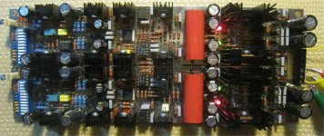
Sure, I did one at the about the same noise or slightly better, about 10 years ago, see attached. Left channel is 0.26nV/rtHz, right channel 0.29nV/rtHz. Could be much lower, but I wanted it for high input impedance (at that time I had a 2mV high output MC cartridge which was optimized for 47k input impedance), so some trade off was unavoidable (input stage is emitter follower with no gain, but it adds to the input referred noise another Rbb). The input current noise was about 3.7pA/rtHz, so it is good up to 40-50ohm source impedance without impacting the overall noise. Rohm 2SD786/2SB737 transistors.
Full schematics including the RIAA stages and Gerbers on my web site; it was built by a bunch of people, always with very good results.
Attachments
Last edited:
When people talk about pV/sqrt Hz, would simulations with noiseless power supplies still be valid ?
Does it say anything about PSRR ?
It also seems that noise is the only critieria because it is low level MC.
So one can hide behind that with circuits which distort more than other or with poor input impedance, etc. ?
Not being a guru, I should refrain from joining the discussion.
But it is still very educational for me, and at times also entertaining.
Cheers,
Patrick
Oh, incidentally, before claiming to be able to "throw bits out & get better performance", perhaps it is advisable to build in real life first.
At least for the CEN / SEN IV, I know what the consequences would be if I threw bits out.
In real life, that is, not in Spice.
Patrick
At least for the CEN / SEN IV, I know what the consequences would be if I threw bits out.
In real life, that is, not in Spice.
Patrick
When people talk about pV/sqrt Hz, would simulations with noiseless power supplies still be valid ?
No, not at all. To my experience, power supply noise injection is the largest contributor to excess noise (on top of what an accurate simulation of the signal path predicts).
Needs extreme precautions to avoid; I went so far to use buffers with a CFP series element, built from a medium power transistor (rather high Rbb) and another ultra low noise transistor as driver; this way, the local feedback loop cancels the effect of the high Rbb and shows only the driver low Rbb in the output noise. This, and the input stage gain, makes the power supply input referred noise contribution negligible. The PSRR of any gain stage without active load (which has its own noise problems) is usually crap.
Even a carefully tweaked Jung/Didden regulator, built with the lowest noise opamps, doesn’t go much under 5nV/rtHz output noise, which was not good enough, don’t ask me how I learned this
Buffers as above are still required to avoid power supply noise injection. The other easy way out of the PSRR crapola is massive paralleling of low noise opamps, but then good luck with the input current noise, Gerhard version has (according to the data sheet) some 25pA/rtHz, which makes it useless for source impedances over a few ohms, not many MC cartridges will fit in.
- Home
- Source & Line
- Analogue Source
- Richard Lee's Ultra low Noise MC Head Amp