> To my experience, balanced phono designs are an useless luxury.
If you are only considering noise, maybe.
I use balanced throughout because of even harmonics cancellation.
Even harmonics can be >30dB lower than single ended if you match properly.
A simplified universal differential or single ended phono preamp
But each to his own taste,
Patrick
If you are only considering noise, maybe.
I use balanced throughout because of even harmonics cancellation.
Even harmonics can be >30dB lower than single ended if you match properly.
A simplified universal differential or single ended phono preamp
But each to his own taste,
Patrick
> To my experience, balanced phono designs are an useless luxury.
But each to his own taste,
Patrick
I assume syn08 is referring to conventional high feedback topologies. One would be hard pressed to measure the distortion of an amplifier with test LP's in any case.
I assume syn08 is referring to conventional high feedback topologies. One would be hard pressed to measure the distortion of an amplifier with test LP's in any case.
Fully agreed, but the question was not amp distortion but suppression of induced noise in the cabling.
Hans
Fully agreed, but the question was not amp distortion but suppression of induced noise in the cabling.
Hans
I think Patrick was talking about low or no feedback amplifier topologies and cancellation by symmetry. I have not done extensive experiments with single ended vs differential phono but in a couple of limited tests the differential was a slight improvement.
> To my experience, balanced phono designs are an useless luxury.
If you are only considering noise, maybe.
I use balanced throughout because of even harmonics cancellation.
Even harmonics can be >30dB lower than single ended if you match properly.
A simplified universal differential or single ended phono preamp
But each to his own taste,
Patrick
No, I was thinking from a hum sensitivity perspective. Distortions are irrelevant anyway, my high feedback stuff is also an useless "because I can" luxury.
BTW, the WK design is as "high feedback" as you can get. The chosen gain of 631 is to me way to high to provide a good dynamic range. It also appears to me (by inspection) that the servo time constant R=150k C7=330n is too low (some 3Hz), resulting in a significant LF overshoot).
Last edited:
Thanks Scott.I have not done extensive experiments with single ended vs differential phono but in a couple of limited tests the differential was a slight improvement.
Hans
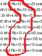
I opened the LTSPICE included models file, values for RB are clearly made up.
Scott,
In which version of LTSpice did this pop up and what was the name of this file ?
In the Bipolar Transistors.lib file, I can’t find anything of that kind.
Hans
No, I was thinking from a hum sensitivity perspective. .
It is a valid question whether coil hum pickup is all DM or has a CM component. Should be easy to test grounding one leg of a diff in MC stage? I have found someone who can rewind a cartridge with a centre tap. I may take him up on it when I want to transcend new heights of pointlessness
")
Hans, can you do THD on both circuits at 150uV, 50uV, 15uV & 5uV in addition to Bonsai's 500uV? Same 4R3 & currents please.
Thanks for this Hans.Here it is:
Damn! No clear winner.
Should I suggest a few more tweaks to improve JC's circuit? Don't want to give da false prophet too much credence
Scott,
In which version of LTSpice did this pop up and what was the name of this file ?
In the Bipolar Transistors.lib file, I can’t find anything of that kind.
Hans
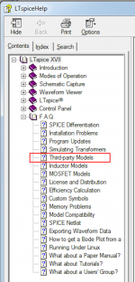
The online help system gives the file name and its location. You can find it in the section of the Help tree named Third Party Models (red box in screen image below)
_
Attachments
Scott,
In which version of LTSpice did this pop up and what was the name of this file ?
In the Bipolar Transistors.lib file, I can’t find anything of that kind.
Hans
Drop a transistor down and right click, it asks if you want to pick a model. The model file is all strung out on the line for each built-in model.
Proper extraction of RB and RE would come from both a noise vs IC plot and a plot of log conformance. The log conformance requires T also. I don't know of anyone that does this because for 99% of the applications (now) these are trivial parasitics.
Actually Rnv is half 1/gm for a 'perfect' BJT... but the minimum noise of a bipolar transistor should be 1/gm thermal noise.
Baxandall explained it in his 1967 article which is in MicBuilders. It was this project that finally led to my understanding as I was playing with near 'perfect' BJTs and the circuit had no other noise sources. I was getting exactly the predicted noise.
Common base has Rni 2 x 1/gm which is how you get best NF 3dB if properly matched.
The Great Guru did an even clearer explanation near the end of his life when he analysed Graeme Cohen's mike preamp, the quietest in da known Universe. Millenia Media use this as does the Earthworks (the quietest you can buy) though neither have as good real life performance.
Can't remember where I saw this later article.
I'm surprised Guru Wurcer didn't pick this up as he is possibly the greatest LN guru still alive
I've done so for mine and for any BJTs I have reliable rbb' estimates. I'm only a pre10 LTspice guru but can't see or have encountered any problems setting RB to 1R2 & 1R5 for other stuff like PA design.Bonsai said:I propose we change the (ZTX851/951) model(s) to reflect H&H AoE figures then.
If you don't do this, you won't get the levelling out of Rnv with higher current that Wayne and H&H measure .. which is indeed how I (and they) got my guess
Please post EXACTLY how you do this balanced to single ended, if you have such a real vinyl playback system which has hum stuff clearly less than 280pV/rt(Hz)Syn08 said:To my experience, balanced phono designs are an useless luxury. There's nothing they can practically provide that a good shielded balanced to single ended signal cabling cannot solve.
This is a serious request.
My LTspice model file has nearly half the BJTs with RB=1 and some even lessScott Wurcer said:I opened the LTSPICE included models file, values for RB are clearly made up. pic with loadsa RB=10
I immediately contacted the LTspice shop but they told me they were all out of stock of these devices. OK, which of you has bought them all up?
Actually Rnv is half 1/gm for a 'perfect' BJT.
I'm surprised Guru Wurcer didn't pick this up as he is possibly the greatest LN guru still alive
I did, got distracted. It comes from the same 2 in sqrt(2qI), the collector shot noise. There is still a problem with all these sims being posted with nonsense models.
That circuit BTW was published in 1968 by Bob Demrow and rumor was it came from a customer using moving coil geophones looking for oil. These are typically used in large arrays with sometimes 100's of feet of cable.
Wiring schematic is attached. There is an optional 1nF cap from each channel input ground to the case ground, not figured. The link between the channels signal grounds is also optional.
The cable schematic is also attached (from Self). Here, GROUND at pin 1 is the tone arm metal shell, pins 2 and 3 are the cartridge.
My bad, it’s indeed half of 1/gm. I simulated a bipolar transistor using RB=0 and I got exactly the expected result (using pspice, not LTSpice).
The cable schematic is also attached (from Self). Here, GROUND at pin 1 is the tone arm metal shell, pins 2 and 3 are the cartridge.
My bad, it’s indeed half of 1/gm. I simulated a bipolar transistor using RB=0 and I got exactly the expected result (using pspice, not LTSpice).
Attachments
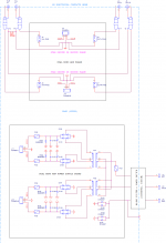
Thanks for this syn08. This is indeed how you should wire unbalanced for very low noise & long leads.Wiring schematic is attached. There is an optional 1nF cap from each channel input ground to the case ground, not figured. The link between the channels signal grounds is also optional.
The cable schematic is also attached (from Self). Here, GROUND at pin 1 is the tone arm metal shell, pins 2 and 3 are the cartridge.
In da old days, many Old World tone arms and preamps used 5p DIN connectors which allowed you to do this (4 cores & screen) right up to the cartridge. Not sure about da rebel colonies.
It was SME which made this unfashionable cos they introduced their EVIL Gold Plated (but crap
) RCA phono cables which became sorta standard in high quality tone arms.But my experience is that there are still situations where fully balanced is advantageous. There's RFI immunity too which is an even longer story
________________________________
Sad that people are prepared to spend $$$ on supadupa mains cables etc but won't spend 2c on something which actually makes things sound betterbillshurv said:Thing is I can use up a tin of altoids quickly (and they are available here now days) but a can of Duraglit takes me about 10 years, and my current silvo tin has a plastic screw top. Kiwi shoe polish tins would work but nowhere for the battery!
Actually getting into replace the battery seems the challenge with this approach. Both my tables have space under the tonearm for the unit but then gets a pain to change the power source. This is the trouble with very simple circuits, you end up angsting things that don't necessarily matter
... not that I'm accusing you Bill. Maybe if I claim Duraglit tins are hand carved from solid Unobtainium by Virgins
You build the circuit including the attached C cell battery holder into the lid of the Duraglit tin. This gives better shielding and easier battery change. If you are using one of higher Rdc cartridges and running 1mA or less, your C cell lasts more than a year.
BTW, the original MicBuilders document that Bonsai has archived explains many of the things we are discussing including the choice of Duraglit over Altoids, genesis of the circuit etc
____________________________
May I conduct a little poll ?
We've had loadsa sims but how about real life examples, actually in use in vinyl playback systems. I've got 280pV/rt(Hz) and I think Wayne has 500pV/rt(Hz) in his balanced system .. both measured as well as simmed.
Any more real life examples?
I really want someone to build both my circuit as well as the modded JC to compare. I'm pretty certain I tried out JCs topology circa 1980 but can't remember what the cons were. Probably to do with EVIL 1000uF caps but I'm guessing from 40 yrs on.
http://www.hoffmann-hochfrequenz.de/downloads/lono.pdf is the only example of measured performance that's sorta pukka. It is, in theory, 0.9dB quieter than mine on the LoZ MCs .. but slightly more complex. Not sure if anyone has tried it on a MC system.
____________________________
Hans, may I ask you label your JC results 'JC modded by Lee'. Guru Wurcer will insist my circuit be labelled 'Leach modded by Lee'. I only improved JC's noise by 4.4dB while I got more than 10dB with Leach
But my experience is that there are still situations where fully balanced is advantageous. There's RFI immunity too which is an even longer story
That's what the 1nF caps I mentioned are for. Good enough even if you live on top of a radio station antenna pole. And of course, one more reason why JFETs are so much better.
- Home
- Source & Line
- Analogue Source
- Richard Lee's Ultra low Noise MC Head Amp