I have a Sony PS-X70 on my bench that isn't doing the one thing every turntable needs to do -- turn! When either Start or Auto Start are pressed, there is no movement of the platter. Nada.
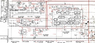
After some work on the power supply board, all of the PS voltages to the main board are correct. Working backwards from the motor, it appears that the issue starts at IC3, prior to the gain adjustment for the Hall Sensors and the motor drive circuit. I should be getting around 1.8V at pin 1, but instead it shows zero. When I bypass IC3 and apply 1.5V DC from an external source, the platter turns. I'm also seeing zero at Pin 3 and at the emitter of Q5. Given these measurements, I'm trying to understand how the circuit is supposed to function to send the correct voltages to pins 2 and 3 of IC3. Is it via Q2, Q3, Q4, and Q5? Or through IC1?
Schematic — imgbb.com
Last edited:
Do you have the sawtooth waveform on pin 1 of the CX193?
Do you see a change in logic level on pin 7 as you operate the start/stop button?
Do you have a very high frequency clock signal on pin 16. This should be running at the frequency of the crystal nearby. It doesn't say what that is in the parts list. Usually if its running its going to be OK though.
Do you see a change in logic level on pin 7 as you operate the start/stop button?
Do you have a very high frequency clock signal on pin 16. This should be running at the frequency of the crystal nearby. It doesn't say what that is in the parts list. Usually if its running its going to be OK though.
Attachments
Actually, I don't have a sawtooth waveform on pin 1 of the CX193. This is what I'm seeing:

The signal at pin 16 looks more like what's shown in the schematic:

For pin 7, the DC voltage changes from 2.0V to a lower value every time I press Start/Stop.
And there's a square wave at pin 8 of the correct peak-to-peak voltage when I turn the platter by hand.
The signal at pin 16 looks more like what's shown in the schematic:
For pin 7, the DC voltage changes from 2.0V to a lower value every time I press Start/Stop.
And there's a square wave at pin 8 of the correct peak-to-peak voltage when I turn the platter by hand.
Pin 16 looks OK, not so pin 1. The big question is whether the sawtooth should be present all the time or whether it is present only in play mode. In other words is something inhibiting the IC or is it a real issue around there.
Might be worth checking C6 by substitution and also making sure that the resistor chain and presets are OK. No need to measure anything for those, just dab a 470k from C6 to the 5 volt rail and see if anything changes.
Might be worth checking C6 by substitution and also making sure that the resistor chain and presets are OK. No need to measure anything for those, just dab a 470k from C6 to the 5 volt rail and see if anything changes.
The service manual lists C6 as "polyethylene" which I found odd. I had a .01 uf polyester film cap in hand, so I used that. No change in the signal. Nor did it change when I touched a 470k resistor between C6t and the 5V rail. Now for what it's worth, the image I got for pin 1 yesterday was not when using my scope probe, but rather a BNC terminated length of R58 A/U that has mini grabber clips on the test end. When I used my probe today, this is what I see (best picture I can get of it, since it's always moving).

What you are seeing on pin 1 looks more like internal leakage of some high frequency signal... assuming it is high frequency, can't tell without the time-base setting on the scope... but its obviously not what it should be.
I'm so reluctant to condemn the chip because usually faults often tend to be anything but 'the big IC' and yet at this stage I suppose you have to try it if only to rule it out.
When you have been around the chip looking at all the inputs to it... well then its time to consider.
What would I do... probably pull Q3 out and see if that changes anything. Is it doing something weird with the on/off flip flop input? Pull it and see.
There isn't much else I can suggest at this point tbh.
I hear you about the CX193. A few days ago I was ready to swap it out, but something keeps nagging at me that there's a different culprit at play. 
Regarding Q3, I replaced it with a new one the other day, so probably not worth the test of pulling it I'm guessing.
Thanks for the help. I'll order a new CX193 and report back.
Regarding Q3, I replaced it with a new one the other day, so probably not worth the test of pulling it I'm guessing.
Thanks for the help. I'll order a new CX193 and report back.
Last edited:
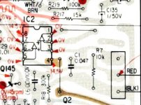
IC2 is a dual opamp and is shown with only one half in use.
Its also shown with pin 3 floating which would be really bad design if true. In any case, the readings on those three pins could be anything depending on what pin 3 is connected to.
Its worth checking for curiosity. With pin 1 and 2 connected these two pins should follow the voltage on the input (pin 3). The board layout seems to show pin 3 connected to the top pin of a group of three.
If that connection is floating then that is why the readings are as they are (and that is bad design), your meter is reading a floating pin 3 and when the meter isn't connected pins 1 and 2 just reflect whatever pin 3 has floated to.
Its probably all normal and in any case you have checked the important FG signal from the other half of the opamp.
Attachments
Sounds like it.
With pins 1 and 2 connected the opamp behaves as a voltage follower (buffer) and the output will be whatever is applied to pin 3. Its very bad design to leave input pins floating and it would have been far better if they just connected pin 3 to pin 7 so that the unwanted half just followed what the other side was doing.
With pins 1 and 2 connected the opamp behaves as a voltage follower (buffer) and the output will be whatever is applied to pin 3. Its very bad design to leave input pins floating and it would have been far better if they just connected pin 3 to pin 7 so that the unwanted half just followed what the other side was doing.
What you are seeing on pin 1 looks more like internal leakage of some high frequency signal... assuming it is high frequency, can't tell without the time-base setting on the scope... but its obviously not what it should be.
I'm so reluctant to condemn the chip because usually faults often tend to be anything but 'the big IC' and yet at this stage I suppose you have to try it if only to rule it out.
When you have been around the chip looking at all the inputs to it... well then its time to consider.
What would I do... probably pull Q3 out and see if that changes anything. Is it doing something weird with the on/off flip flop input? Pull it and see.
There isn't much else I can suggest at this point tbh.
So we've ruled out IC1. I replaced it with a new CX193, and there's no change. Can't say I was surprised.
It had to be tried I suppose
One area worth exploring... trace pin 2 back to the user controls for pitch adjustment. What going on around that area?
It looks as though with the pitch option set to OFF that there should be a half supply reference voltage (2.5 volts) at the junction of R5 and R6.
One area worth exploring... trace pin 2 back to the user controls for pitch adjustment. What going on around that area?
It looks as though with the pitch option set to OFF that there should be a half supply reference voltage (2.5 volts) at the junction of R5 and R6.
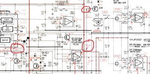
One related observation: I see 2.8V at pin 7 of IC3, but I should be getting 0V. Same goes for the inputs of that opamp: Both pins 5 and 6 of IC3 are showing 2.8V, which originates at pin 21 of IC1.
Also, the 2.8V between R5 and R6 is there regardless of the Pitch control being on or off.
Also, the 2.8V between R5 and R6 is there regardless of the Pitch control being on or off.
Last edited:
I have 2.8V at the junction of R5 and R6. I'm also seeing the full reference supply voltage on the one side of R4.
That sounds OK.
The static DC voltages at the output of IC3 should follow what you see on pin 21, however IC3 is configured as a filter/integrator meaning it provides an average DC output based on the duty cycle of the squarewave on pin 21, which I'm assuming isn't present and its just a static DC voltage you are seeing there.
Also there are three voltages marked which don't seem to agree with each other.
I think you have to concentrate on why the sawtooth oscillator (pin 1) isn't running and whether that oscillator should run all the time or whether its inhibited by the logic in some way.
Attachments
That sounds OK.
The static DC voltages at the output of IC3 should follow what you see on pin 21, however IC3 is configured as a filter/integrator meaning it provides an average DC output based on the duty cycle of the squarewave on pin 21, which I'm assuming isn't present and its just a static DC voltage you are seeing there.
Also there are three voltages marked which don't seem to agree with each other.
I think you have to concentrate on why the sawtooth oscillator (pin 1) isn't running and whether that oscillator should run all the time or whether its inhibited by the logic in some way.
If I recall correctly, I saw a sine wave on 21 instead of the expected square wave.
Also, fwiw I rechecked the waveform on pin 8 while spinning the platter, and it's a less than square square wave.

I'll focus on pin 1 as you suggest. Thanks.
Pin 8 is fine. Its just a feedback signal of frequency related to the platter speed.
I've no bright ideas on the oscillator tbh other than to cling to the theory it should either be running all the time or at least get enabled as the start/stop flip flop internal to the chip does its thing.
I've no bright ideas on the oscillator tbh other than to cling to the theory it should either be running all the time or at least get enabled as the start/stop flip flop internal to the chip does its thing.
Another thought on all this with it being such an involved and complex design would be to work from the block diagram at the beginning of the manual.
We've check pretty much everything around that chip and not really come up with anything.
Is it possible that some mechanical issue (all the switches) is somehow inhibiting operation. Look for clues. Do the 33/45 rpm lights change correctly, does the repeat LED respond to button presses and so on. There seems to be an optical auto return detector using a bulb and photocell. What about all the cam switches (lower right on the block diagram). There is a start/stop LED. Does that respond. Does the pitch LED light in response to the switch. Up/down button ? Is that arm lift.
I'm just wondering if some input is wrong somewhere and somehow inhibiting operation. Look for clues anywhere you can.
Good thought. All of the control LEDs light up as they should, the arm raises and lowers when Up and Down are pressed, and pressing Auto Start will cause the arm to swing out over the platter and lower (Stop will cause it to go back to the rest).
The only anomaly (if it is one) is that the neon light for the XTAL/speed window does not light up, even if I rotate the platter by hand. According to the SM, I should have 187V and 85V at the Red and White wire pins respectively that go to the neon bulb board. I measure 201V and 88V. There's also an 8.2K resistor at R411, rather than the 12K specified, though it appears to be original.
The only anomaly (if it is one) is that the neon light for the XTAL/speed window does not light up, even if I rotate the platter by hand. According to the SM, I should have 187V and 85V at the Red and White wire pins respectively that go to the neon bulb board. I measure 201V and 88V. There's also an 8.2K resistor at R411, rather than the 12K specified, though it appears to be original.
- Status
- This old topic is closed. If you want to reopen this topic, contact a moderator using the "Report Post" button.
- Home
- Source & Line
- Analogue Source
- Sony PS-X70: Deciphering motor issue