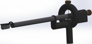
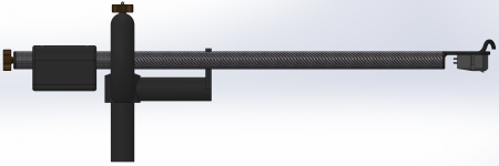
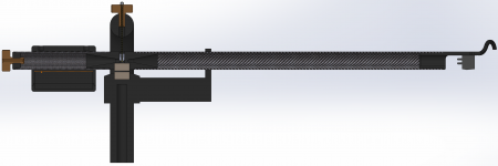
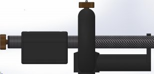
I wanted to share of the details and results from one of my latest (but long term) projects that I finally got around to completing and measuring... a low cost 3D-printed 12" tonearm with a carbon fiber armtube and Schroeder style pivot.
I designed the tonearm specifically for ease of construction, and to use as many off-the-shelf parts as possible so that it would be east for anyone to construct.
It's also quite flexible in terms of armtube length, so pretty much anything from 8" to 12" (or possibly longer) could be constructed simply by varying the armtube length.
The overall idea is that the plastic parts can easily be printed, and overall assembly requires nothing more than some sandpaper, some good CA glue (I used Loctite Black Max) a drill and a bit of patience.
I had serious doubts about the first iteration working at all, but much to my surprise it didn't just work, it went together flawlessly and performs exceptionally well!
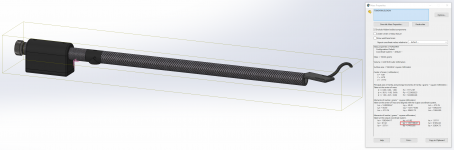
Attached here are some screen captures of the 3D CAD for the arm showing the basic design. In the next post, I will share some images of the completed arm mounted on the prototype table. Following that I will post some preliminary measurements to give people an idea of the performance that can be expected.
On that last note, I would be very curious to hear from those experienced with tonearm design exactly what measurements they would like to see. I have access to an APx555 so I can measure pretty much anything. I also have a copy of Hi-Fi News Analogue Test LP that I've been using as a source of test tones. If there are any suggestions I would be happy to give it a try!
Cheers,
Owen
I designed the tonearm specifically for ease of construction, and to use as many off-the-shelf parts as possible so that it would be east for anyone to construct.
It's also quite flexible in terms of armtube length, so pretty much anything from 8" to 12" (or possibly longer) could be constructed simply by varying the armtube length.
The overall idea is that the plastic parts can easily be printed, and overall assembly requires nothing more than some sandpaper, some good CA glue (I used Loctite Black Max) a drill and a bit of patience.
I had serious doubts about the first iteration working at all, but much to my surprise it didn't just work, it went together flawlessly and performs exceptionally well!
Attached here are some screen captures of the 3D CAD for the arm showing the basic design. In the next post, I will share some images of the completed arm mounted on the prototype table. Following that I will post some preliminary measurements to give people an idea of the performance that can be expected.
On that last note, I would be very curious to hear from those experienced with tonearm design exactly what measurements they would like to see. I have access to an APx555 so I can measure pretty much anything. I also have a copy of Hi-Fi News Analogue Test LP that I've been using as a source of test tones. If there are any suggestions I would be happy to give it a try!
Cheers,
Owen
Attachments
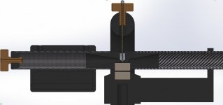
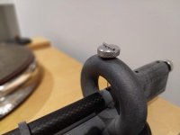
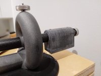
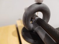
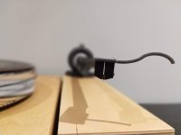
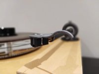
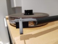
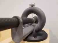
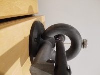
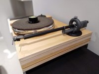
Transitioning to the real world, the images below show the completed prototype tonearm mounted to my prototype table.
Here are some of the construction details:
- Armtube is 15mm OD, 13mm ID carbon fiber tube. It's readily available from AliExpress or any model/RC store, and is frequently used to build tripods and drones. I scored two tubes (enough for two 12" tonearms) for $16.50.
- Magnets are N52 12.7mm diameter and 6.35mm height. I sourced mine from K&J Magnetics for $2.21 each.
- Thumbscrews are M6 x 13mm steel and were sourced from AliExpress for $1.76 each. If I had to do this over again I would use brass or copper in place of steel as a 2mm hole needs to be drilled in one of these, and the steel used in the thumbscrews linked above work-hardens like crazy and is nearly impossible to drill. Brass, on the other hand, would drill like butter.
- Set screws are M5 x 5mm and are available in a bag of 50 for $3 on AliExpress. One of these needs a 1mm hole drilled in it.
- String is Kevlar kite string from Amazon. A 1000ft roll can be had for $20.
- A 2mm steel dowel pin holds the loop of Kevlar string in the upper thumbscrew allowing for independent VTA/height adjust and anti-skate. I just had these laying around.
- Some good quality Loctite Black Max CA holds everything together nicely.
- All 3D printed parts are done using HP's MJF printing process using PA12 material (40% glass bead) for maximum strength and dimensional accuracy.
- Counterweight is made using adhesive backed zinc wheel weights mounted inside the counterweight compartment.
Assembly involves cutting the armtube and counterweight tube to the correct length, and gluing them to the 3D printed magnet mount. One magnet then needs to be glued in the armtube magnet mount, and one into the base ensuring polarity is correct. Once that dries, a perfectly level surface and a level block can be used to glue the headshell into the armtube to ensure it's perfectly straight and square. The rest is just a matter drilling one of the set screws, one of the thumb screws, and then fishing the Kevlar string through. A dab of CA ensures the knot will never come undone.
Results below.
Cheers,
Owen
Attachments
-
 IMG_20190418_213716.jpg439.3 KB · Views: 476
 -
 IMG_20190418_213707.jpg594.9 KB · Views: 462
 -
 IMG_20190418_213654.jpg494.6 KB · Views: 447
 -
 IMG_20190418_213643.jpg297.9 KB · Views: 437
 -
 IMG_20190418_213631.jpg290.7 KB · Views: 482
 -
 IMG_20190418_170146.jpg682.1 KB · Views: 571
 -
 IMG_20190418_170102.jpg611.7 KB · Views: 627
 -
 IMG_20190418_170049.jpg673.3 KB · Views: 609
 -
 IMG_20190418_213726.jpg611.2 KB · Views: 655
Finally, I have a handful of preliminary measurements. These were taken on a the prototype table shown in the picture, and represent the cumulative results of the following chain:
- Hi-Fi News Test LP (1kHz test tone)
- Denon DL-103 MC cartridge
- 3D Printed Tonearm
- The Wire Fully Balanced Phono Preamp
- APx555
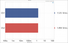
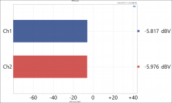
First up we have a basic RMS level test showing that the channels are very well balanced, which should mean the cartridge is properly adjusted in the headshell, and the arm is nice and square to the surface of the record.
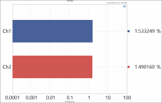
Next we have a distortion measurement also showing excellent balance between channels.
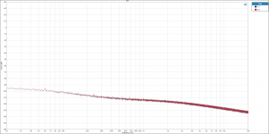
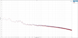
For the next measurement we have an FFT of the noise floor on un-modulated grooves of the test LP.
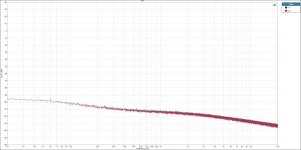
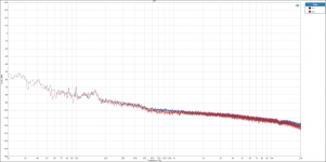
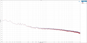
Next is a series of 3 stop-groove measurements at different locations on the LP surface. One middle, one outside edge and one inside edge. I was looking to see how well channel balance matched across the surface of the LP, and see if there was any difference in noise levels.
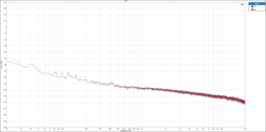
Same as above, but without the platter rotating (belt removed). I'm mostly looking for noise coupling from the motor to the LP. These indicate the motor I've selected is not responsible for any noise coupling into the platter. At least not through the table itself, but possibly through the belt.
Again, if there are any measurements people would like to see here, please let me know. I'd be happy to take a few and report back!
Regards,
Owen
- Hi-Fi News Test LP (1kHz test tone)
- Denon DL-103 MC cartridge
- 3D Printed Tonearm
- The Wire Fully Balanced Phono Preamp
- APx555
First up we have a basic RMS level test showing that the channels are very well balanced, which should mean the cartridge is properly adjusted in the headshell, and the arm is nice and square to the surface of the record.
Next we have a distortion measurement also showing excellent balance between channels.
For the next measurement we have an FFT of the noise floor on un-modulated grooves of the test LP.
Next is a series of 3 stop-groove measurements at different locations on the LP surface. One middle, one outside edge and one inside edge. I was looking to see how well channel balance matched across the surface of the LP, and see if there was any difference in noise levels.
Same as above, but without the platter rotating (belt removed). I'm mostly looking for noise coupling from the motor to the LP. These indicate the motor I've selected is not responsible for any noise coupling into the platter. At least not through the table itself, but possibly through the belt.
Again, if there are any measurements people would like to see here, please let me know. I'd be happy to take a few and report back!
Regards,
Owen
Attachments
-
 Residual Noise - No Motor.png120.3 KB · Views: 93
 -
 Residual Noise - Motor 45RPM.PNG126.5 KB · Views: 92
 -
 Residual Noise - Motor 33RPM.PNG119.7 KB · Views: 104
 -
 stop groove inside edge.png133.8 KB · Views: 103
 -
 stop groove outside edge.PNG144.8 KB · Views: 107
 -
 stop groove middle.PNG128.1 KB · Views: 159
 -
 Unmodulated Grooves 33RPM (2).PNG127.2 KB · Views: 161
 -
 THD Ratio 15db.png76.4 KB · Views: 156
 -
 RMS Level.png76.1 KB · Views: 305
Thanks for the kind words ")
Hi gigigirl,
I tested the resonance in the vertical and horizontal modes, but I lost the paper I had written the results down on. I will have to re-run the test and report back.
I also have a second set of all the individual parts for the tonearm, so I could likely figure out a pretty accurate effective mass using those. I just need to work through the math. I have a very accurate scale, and I know all the dimensions, so it could be a fun task.
I'll report back when I get that sorted out!
Cheers,
Owen
Wow!
My thought
Next make one for b&o tangentials that takes p-mounts. You wuld make thousands happy since b&o has their own mounttype and pickups at almost.umobtainable and expensive. So many exelent b&o turntables in thriftshops that doesnt have a pickup
Hi All,
I fiddled with a few other settings on the table this evening (mostly motor) but also took the time to run the measurements requested.
First up was the horizontal and vertical resonance tests to determine combined resonance of the DL-103 and the arm. The results were 10Hz in the horizontal direction, and 11Hz in the vertical direction. Given most people target 10Hz as ideal, I would say this is a pretty good arm to combine with the 103. This perhaps makes the EM a touch high for some other cartridges, but I only intend to use it with the DL-103.
I may have forgotten to mention it, but this is a 305mm (12") effective length arm which is probably at least part of the reason for the higher EM.
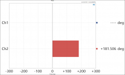
I also ran the Azimuth test tracks on that album, and it's also pretty spot-on. Those are attached here. Channel balance is within 0.1dB and phase is roughly 1.5 degrees out. That's should give very good cancellation which is what that test track is intended to do. I think the picture grayblob referred to is simply showing the cartridge at a bit of an angle because that's how it's resting in the holder.
gigigirl,
I have one spare complete set of parts to build one of these if you're interested, including everything needed to make the arm. If you are interested, please send me a PM and we can figure something out. Are you looking to building the arm yourself, or would you need me to build it? I'd like to have someone build it up and provide feedback if possible.
Regards,
Owen
I fiddled with a few other settings on the table this evening (mostly motor) but also took the time to run the measurements requested.
First up was the horizontal and vertical resonance tests to determine combined resonance of the DL-103 and the arm. The results were 10Hz in the horizontal direction, and 11Hz in the vertical direction. Given most people target 10Hz as ideal, I would say this is a pretty good arm to combine with the 103. This perhaps makes the EM a touch high for some other cartridges, but I only intend to use it with the DL-103.
I may have forgotten to mention it, but this is a 305mm (12") effective length arm which is probably at least part of the reason for the higher EM.
I also ran the Azimuth test tracks on that album, and it's also pretty spot-on. Those are attached here. Channel balance is within 0.1dB and phase is roughly 1.5 degrees out. That's should give very good cancellation which is what that test track is intended to do. I think the picture grayblob referred to is simply showing the cartridge at a bit of an angle because that's how it's resting in the holder.
gigigirl,
I have one spare complete set of parts to build one of these if you're interested, including everything needed to make the arm. If you are interested, please send me a PM and we can figure something out. Are you looking to building the arm yourself, or would you need me to build it? I'd like to have someone build it up and provide feedback if possible.
Regards,
Owen
Attachments
Hi Naz,
I'm happy to share the files, but there are a few caveats:
1. Absolutely no commercial sales of these parts.
2. No unauthorized group buys.
3. Personal use only.
4. I am not responsible if you spend a bunch of money printing these parts and your tonearm doesn't work out.
Some additional printing info:
Not all printing methods are the same when it comes to plastic 3D printing. I know this is stating the obvious for some, but this is an important thing to note. There is a massive difference in the accuracy of the prints, the strength of the parts, the materials and properties of the plastics, and the stability, longevity, machine-ability, and compatibility of the various parts. Some parts need to be tapped for M5 or M6 threads, and this probably isn't possible with some 3D printing methods. Here's a link to a very good set of articles explaining all this if you're new to 3D printing:
HP MJF vs. SLS: A 3D Printing Technology Comparison | 3D Hubs
If you try and print these parts on a low end extruding type (FDM) printer, I can almost guarantee they will not work. The dimensional accuracy and strength of the resulting parts will probably not result in a workable tonearm. You might be able to get it to work with some advanced tricks and post-processing, but it's not a great place to start.
I know the parts coming off HP's MJF printer are of excellent quality, and exhibit good dimensional accuracy and excellent strength. The parts shown here were printed on this process. I would imagine SLS, SLA, and DLP prints would also work pretty well. The base and the armtube magnet mount both include internal tunnels for wire routing that would not be possible to machine or mold.
If there is sufficient interest, I would definitely consider doing a small production run of the kits, but it would not be done at cost, as endeavors like this take a great deal of time and effort. A complete kit would probably be in the $300-$350 ballpark for all the parts needed to build a complete arm.
If people are interested, please let me know and we can start a list. I think at least 10 arms would be needed to make it worthwhile.
Regards,
Owen
Attachments
Hi All,
I spent a few hours looking into the effective mass of the arm, and came up with some very interesting findings.
For the effective mass, I started by doing a rough calculation based the following method:
Measuring Tonearm Effective Mass- Vinyl Engine
I attached what is possibly the most nonsensical spreadsheet I've ever made, but all the numbers are in there (somewhere!). You will need to change the file extension back to .xlsx to open it. The short story on this rough method is that the counterweight side of the arm has an MoI of 0.00051837kgm^2 and the cartridge side has an MoI of 0.000677013kgm^2 which gives a total MoI of 0.01195383kgm^2. With an effective length of 305mm, the effective mass of the 12" arm calculates out to 12.85g The trouble with this method is that is kinda lumps several parts together, ignores other parts, and assumes a perfectly even unit mass on the armtube side.
But... I have very accurate CAD of the arm, and Solidworks is a very powerful tool when it comes to stuff like this
What I decided to do was reconcile my CAD with the real world weights of all the finished parts, and add proper densities to the parts in CAD to get very accurate weight for every single part in the CAD model. From there, I could use the Solidworks "Mass Properties" feature to calculate the true MoI for the whole arm with a great deal of accuracy.
All the measured weights for the parts are shown in the spreadsheet, and those were used to input densities for the materials of all parts in the CAD. I set the origin to the central pivot point of the whole armtube assembly, then let Solidworks calculate the accurate MoI for the counterweight side, the cartridge side, and the whole arm. A screen capture of this is attached.
Long story short, Solidworks calculated a pretty similar, but somewhat higher MoI for the counterweight side, and a much higher MoI for the cartridge side:
Total MoI from CAD (counterwight side) 571314.55 g/mm^2
Total MoI from CAD (cartridge side) 791609.17 g/mm^2
Total MoI from CAD 1361108.82 g/mm^2
Using these numbers, and the same effective length I get an effective mass of 14.63g which I believe to be very accurate. The only thing this doesn't account for is the tonearm wire and cartridge clips. This likely increases the effective mass a small amount.
This lead me to the next obvious question... if the effective mass was so much lower than the "suggested" 25g, then why are my measured vertical and horizontal resonances spot on where they should be (~10-11Hz)?
I did some digging on this, and it turns out the whole idea of the DL-103 needing a 25g effective mass is kind of a misunderstanding. It's based on a compliance which Denon specifies at 100Hz when traditionally the compliance is specified at 8-12Hz. Others have reported a resonance of 10Hz using a 16g effective mass arm, so 11Hz with my ~15g of effective mass is about right. Thread link here:
What tonearm is recommended for the denon 103r | Audiogon Discussion Forum
So the executive summary would be:
- The effective mass of this arm is ~14.6g without tonearm wire.
- The Denon DL-103 does not need 25g of effective mass, 15g-16g is spot on.
- The ~14.6g of effective mass results in a resonance of 10-11Hz.
- If you wanted to increase the effective mass of the arm the easiest way would probably be to heat shrink or wrap the arm in electrical tape.
Hope this helps!
Regards,
Owen
Attachments
Your addition is out by a factor of ten. This is why scientific notation is great, no miscounting of zeroes: 5.18e-4 + 6.77e-4 ~= 1.2e-30.00051837kgm^2 and the cartridge side has an MoI of 0.000677013kgm^2 which gives a total MoI of 0.01195383kgm^2. With an effective length of
Also you quote completely spurious 6 digit precision - 2 or 3 figures are plenty for this.
Actually that could help damp arm vibrations too, so a double win. Though electrical tape tends to get sticky and horrible, and cooking your tonearm to shrink heatshrink might damage something.- If you wanted to increase the effective mass of the arm the easiest way would probably be to heat shrink or wrap the arm in electrical tape.
Your addition is out by a factor of ten. This is why scientific notation is great, no miscounting of zeroes: 5.18e-4 + 6.77e-4 ~= 1.2e-3
Also you quote completely spurious 6 digit precision - 2 or 3 figures are plenty for this.
Hi Mark,
Good catch. Luckily that was just a typo when I transcribed. The rest of the math in the spreadsheet appears correct.
As for scientific notation... I find it a pain to use in spreadsheets, but to each his own.
Significant digits? The outputs were copied in from CAD, the math was all done in the spreadsheet, and the results were presented rounded to one decimal place in the summary. Not sure what the problem is here. I may have done it differently if I was adding everything on a sheet of paper
Regards,
Owen
- Status
- This old topic is closed. If you want to reopen this topic, contact a moderator using the "Report Post" button.
- Home
- Source & Line
- Analogue Source
- Low Cost DIY 3D Printed Tonearm with Carbon Fiber Arm Tube