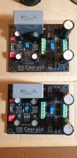
Well that was fun, 1st part done, populated two boards.
Used a square 2.2µF capacitor for neatness. Doubt I'll notice difference
KEMET Part Number: R60QW42205030KR60, Film, Metallized Polyester, Automotive Grade, 2.2 uF, 10%, 1000 VDC, 85°C, Lead Spacing = 37.5mm
"Typical applications include blocking, coupling, decoupling, bypassing and interference suppression in low voltage applications"
I have some audio ones as well to try/compare. do let me know if these are totally unsuitable and/or others that are square
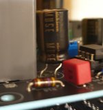
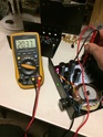
I had to bend the pins for 2 of the Nichicon KZ Muse 100µF capacitators as per photo 2 so they fitted properly
Used a square 2.2µF capacitor for neatness. Doubt I'll notice difference
KEMET Part Number: R60QW42205030KR60, Film, Metallized Polyester, Automotive Grade, 2.2 uF, 10%, 1000 VDC, 85°C, Lead Spacing = 37.5mm
"Typical applications include blocking, coupling, decoupling, bypassing and interference suppression in low voltage applications"
I have some audio ones as well to try/compare. do let me know if these are totally unsuitable and/or others that are square
I had to bend the pins for 2 of the Nichicon KZ Muse 100µF capacitators as per photo 2 so they fitted properly
Attachments
Um.... need to change them then?
Here are some numbers for dissipation factor (DF), smaller is better:
Polyester (PETP) .5%
Polycarbonate .05%
Polyphenylene sulfide (PPS) .05%
Polystyrene .05-.02%
Polypropylene .025-.01%
Teflon (PTFE) .025-.01%
These numbers were culled from over 100 documents on the web.
from metalized polypropylene vs metallized polyester? | Headphone Reviews and Discussion - Head-Fi.org
Shame I liked the look of them on the board......
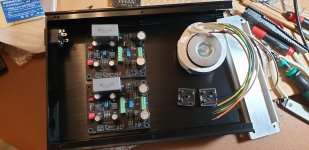
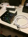
Enclosure layout
I have found a nice sized box(whd 215x55x308 external, 203.5x48x297 internal), not ideal to have transformer in same box but is neater. I worry about mains hum, so....
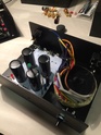
Two choices now, Put Transformer furthest away from the rear and the mains input, and hence shortest phono connections or vice versa?
picture is where the transformer is furthest away, putting phonos on same back panel as the mains input.
I have found a nice sized box(whd 215x55x308 external, 203.5x48x297 internal), not ideal to have transformer in same box but is neater. I worry about mains hum, so....
Two choices now, Put Transformer furthest away from the rear and the mains input, and hence shortest phono connections or vice versa?
picture is where the transformer is furthest away, putting phonos on same back panel as the mains input.
Attachments
@keland
A long thin chassis will always present this dilemma. I recommend to keep the standard position of the connectors in the back, bringing the AC line from the rear socket to a front power threading the wire down the side of the chassis and keeping the transformer and diodes in the front, with the PCBs at the rear close to the input RCA jacks. A metal divider or box enclosing separating the AC power line from the PCB may help with noise pickup, but a lot of the coupling is inductive, so it won't be a definitive solution.
@AnthonyA
R2 = 400 ohms, R3 = 15 ohms Your gain setting is on the high side, circuit noise will increase proportionately.


My Emerald boards are ready for power up. I did not find instructions on how to setup the Emerald phono stage boards from powering them up and biasing if any required. Also not sure what is the purpose of that trimmer on each of the mono board.
Can someone let me know the instructions of powering them up from the bridge rectifiers where I have a +/-12VDC. What should I check if the boards are working fine before I connect to the turntable.
Thanks
Can someone let me know the instructions of powering them up from the bridge rectifiers where I have a +/-12VDC. What should I check if the boards are working fine before I connect to the turntable.
Thanks
- Home
- Source & Line
- Analogue Source
- RJM Audio Emerald Phono Stage Help Desk