Hi,
So first thing is you are unlikely to be able to use the OPA827 for IC1 on account of the output offset voltages being too high. (75 uV typ vs 25 uV typ for the OPA27). You can get away with just about it if you keep the Emerald in MM mode as you propose. 60 dB DC gain means 75 mV (150 uV datasheet max). In MC mode that would increase to 750 mV / 1.5V...
In MM mode the first stage gain is about 3x or 10 dB. It depends a little on which BOM configuration you choose an you can calculate it as (totalMMgain - 30 dB) as the second stage is always 30 dB.
Opa827 (75uV/150uV) x 1000 = 75mV/150mV max, ...but even so, it's probably a lot
OP27EPZ (10uV/25uV max) x 1000 = 10mV/25mV max, - price 9,53€ / 3 nV/√Hz at 1khz
AD797BRZ (10uV/40uV max) x 1000 = 10mV/25mV max, - price 17,20€ / 0.9 nV/√Hz at 1khz
Richard, could I also use the AD797 at positions IC1 and IC2 ?
OP27EPZ (10uV/25uV max) x 1000 = 10mV/25mV max, - price 9,53€ / 3 nV/√Hz at 1khz
AD797BRZ (10uV/40uV max) x 1000 = 10mV/25mV max, - price 17,20€ / 0.9 nV/√Hz at 1khz
Richard, could I also use the AD797 at positions IC1 and IC2 ?
1. The DC gain of the Emerald configured as a MM stage with 40 dB midband gain is 60 dB before the output coupling cap brings it to zero.
2. No, the AD797 is unlikely to work with the Emerald because the boards and circuit layout are not designed with this very specialist IC in mind. (The last time someone experimented with this was back with the Phonoclone, but nothing fundamental has changed that would indicate any different result here.)
2. No, the AD797 is unlikely to work with the Emerald because the boards and circuit layout are not designed with this very specialist IC in mind. (The last time someone experimented with this was back with the Phonoclone, but nothing fundamental has changed that would indicate any different result here.)

@daemonsgr Sure, both MM and MC gain settings are configurable at the time of build by changing the resistor values.
Please download the design manual from the website for details.
Please download the design manual from the website for details.
Hello,I will be using an external PSU that provides ultra low noise +/- 12V.
I will be wiring them to the V+, V- and REF pads, or to the relevant pad in Q5 and Q7.
I will be omitting the marked section in the PCB, but my question is whether I should also omit C6-C13 or are they required for local bypass?
I am also thinking of connecting an external PSU (linear) like you. Did your idea of connecting an external PSU come true? If you did, how did it happen? I would be very happy if you share it.
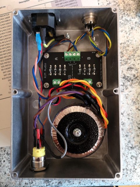
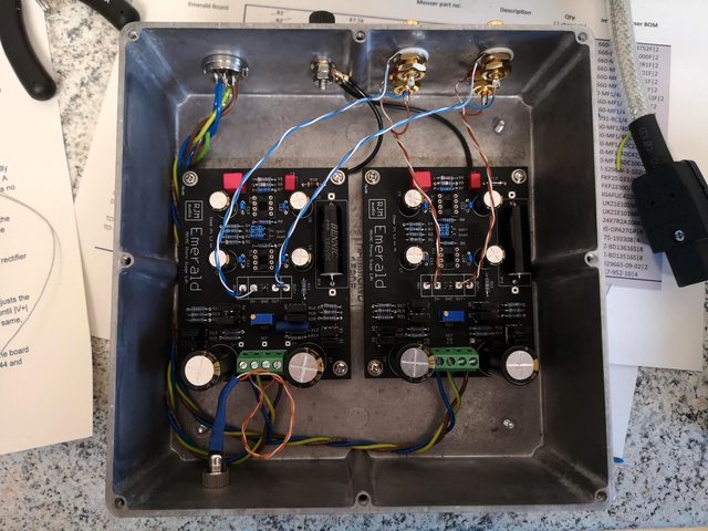
I finally got around to completing the build of the phono stage! The kit has been sat staring at me for a year or so to the side of my desk, so a few rainy days last week gave me the opportunity to get cracking. The most tedious process for me was putting the resistors onto the boards. I'm colour blind (reds and browns) and I did pretty well identifying each resistor value by eye and then verifying with a multimeter. I used my temperature-controlled soldering iron which I picked up from AliExpress - Quicko T12-955, I did have a little difficulty with the smaller pads but managed to get a very good "Hershey's kiss" style solder joint.
I also took the time to tidy up the wiring in the power supply unit, and also noticed a mistake I'd made with the power LED indicators I'd fitted with no current limiting resistor! These are rated at 12V and have a base voltage of 2.8V @ 20mA, although I found for the anti-vandal switch in the power supply that a 2.2k resistor was fine with no noticeable drop in light output (this LED was also wired up with a braided copper cable). In the phono stage I was using an anti-vandal LED pilot with the same specifications but found that the 2.2k resistor was getting very hot (too hot to touch), I'd wired this one with the same solid core UTP cable I'd used for the audio signal cables, so made the assumption that the cable in the power supply was providing some resistance which the UTP cable did not. I upped the resistor to a 4.7K which gets warm but can be held between fingertips without feeling too hot. Incidentally using the LED specifications and the following formula was suggesting an even lower value resistor which would have allowed the LED to draw even more current!
R = (12 - 2.8) / 0.020
= 460 ohms
That brings me on to the other peculiarity I found when testing the voltage coming out of the power supply, I was seeing around 18V on both - and + although this was dropping down to the expected 12.7 - 13V when tested at the test points on the phono stage.
First listening impressions with my Technics 1200 GR and Goldring 1042 MM vs my recapped NAD 314 were astonishing, the sound stage was extremely wide and well defined, I stayed up well past my bedtime spinning discs and enjoying the new sound. I've ordered a pair of Audyn MKP Plus 2.2uF 800V to replace the Bennic caps so can't wait to see if there are any obvious differences. I also managed to get a new Audio Technica AT33PTG/II MC cartridge from Amazon which had been reduced by £100, I took a while making the decision but glad I did as a few days later the price had gone back up to the original.
Many thanks Richard and everyone else for sharing your builds and providing ideas. Here are a few pictures of my build!
Thanks
@dlknight Thanks for contributing your listening impressions as well as the detailed build notes.
Your build is very similar to mine, but I tip my boxes upside down so the lids are concealed and the units have a /---\ taper rather than \---/.
18 V (DC) is the normal voltage at the V+ and V- board inputs. You start with 12 V (AC) out of the secondaries, which generates 18 V (approx) DC after the rectifier diodes. The 18 V is brought down to about 12-13 V by the voltage regulators on the boards.
Richard
@rjm thank you - I had thought about having the boxes upside down but wasn't sure how the internal cabling would work (unless the boards were attached as they are now and suspended from the top).
Of course, I should have realised that the output from the rectifiers would be higher voltage!
My Audyn caps have arrived, so looking forward to swapping them in soon and listening to any discernible differences.
I also have one of your Switchboard kits, but not sure I need it at the moment with the cartridges I am using (Goldring 1042 and Audio Technica AT33PTG/II). Will need to have a think about how it will fit into the box, and also think about adding some switches for swapping from MM to MC function.
- Home
- Source & Line
- Analogue Source
- RJM Audio Emerald Phono Stage Help Desk