OK - It's getting late in the UK for puzzling out wiring diagrams, but it looks like the bottom right terminal may simply be a support terminal for the 200k resistor and that the 4 (K) 150 cap is a substitute for the failed can cap.
I hope Ralph will come back with his opinion.
Here's a pertinent question - did the motor run smoothly before you started the refurbishment? If so, we may be agonising over nothing!
I hope Ralph will come back with his opinion.
Here's a pertinent question - did the motor run smoothly before you started the refurbishment? If so, we may be agonising over nothing!
Well, that would have been good to know at the outset of this thread!Well, when I got it I turned it on and got zapped. A short somewhere.
")
In the absence of any other opinions, I suggest you reinstate the circuit minus the can capacitor. You will have to support the 200k resistor along with the neutral and black connections some other way. Then measure the resistance between line and neutral (with switch at on position) and report back before 'going live'.
No Jim, I do not own this table.
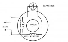
If a 'single-value capacitor motor', the main winding will be connected directly across line and neutral.
The auxiliary winding and series capacitor combination will also be connected across line and neutral.
Compare with the circuit diagram in post #6 where the 'run leg' is the main winding and the 'start leg' is the auxiliary winding.
Attachments
How can you not get a measurement?Hello again Galu. I measured resistance on the motor wires. I got 309 ohms black to brown, 175 ohms black to gray. I don't get a measurement from brown to gray?
Thank you,
Jim
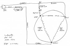
How or why I don't get a measurement I can not say....but I don't. Since my last post I wired the motor up as per the schematic I drew and posted earlier. The motor seems to run just fine. I just interpreted the three terminals on the bad can capacitor as connection points. I left the can cap out and wired as such. Again, motor is running now and seems fine.
Thank you,
Jim
Thank you,
Jim
Re resistances:
black/brown, 309Ω, would appear to be the run winding.
black/grey, 175Ω, would appear to be the start winding.
If that is correct, then brown/green should have been the sum of the two, 484Ω.
How hot is 'very hot'? Too hot to touch?
Assuming that the motor windings are OK, my next step would be to lubricate the bearings and install a motor run capacitor of the correct value.
Last edited:
OK. I think my meter battery was weak. I now get 490 ohms brown to gray so that is good. Yes the motor is to hot to leave your hand on for a second or two. I have a digital tach and it is running at exactly 1800 RPM which is the figure on the motor spec plate. I have already completely disassembled the motor, cleaned well, and re-lubricated.
I checked amperage draw and it is .37 amp whereas the spec plate lists .1 amp. I have a 4 uF cap on order but it won't be here until sometime next week. I will report the results then. From the research I have done, a to large capacitor can cause overheating due to larger current draw?
From my research >
"If the wrong run capacitor is installed, the motor will not have an even magnetic field. This will cause the rotor to hesitate at those spots that are uneven.
This hesitation will cause the motor to become noisy, increase energy consumption, cause performance to drop, and cause the motor to overheat."
Whether the capacitance is too large or too small, the life of the motor will be shortened due to overheated motor windings.too large capacitor can cause overheating due to larger current draw?
Run capacitors must be replaced with the exact value of capacitance.
A quick search does not come up with a 3.7μF motor run capacitor, and a 4.0μF 5% substitute is as close as you are likely to get.
While we await the arrival of the run capacitor:
Your original wiring diagram in post #1 shows a 2kΩ resistor connected across the black & grey wires.
If my interpretation of the motor wiring is correct, this would place the resistor in parallel with the start winding.
This resistor is not visible in your photos, could you have got its position wrong?
- Home
- Source & Line
- Analogue Source
- Need Help With CEC FR-808 Turntable Wiring