Hi. Trying to fix a Naim NAT-01 tuner for a friend. The external power supply is ok, but the tuner is not working. Opened the unit and there is a lot of circuitry into this little one. A service manual, or at least a schematic would be of great help. The guy tried to send it to the autorized Naim dealer in Montreal, but was told the unit was too old, and it is no longer supported...
Let me know if you get something that can help me.
Thanks in advance
SB
Let me know if you get something that can help me.
Thanks in advance
SB
Since I didn't receive any schematic I decided to have a look before calling it off. As I said the external power supply seems ok, producing various nice DC voltages: 26.7Vdc, 24.2Vdc, 14.8Vdc, 5.0Vdc and 4.6Vac (directly from power transformer...
The tuner display is on, but dim, possibly from age, the tuning pot is working and sending tuning voltage to the front end varicap diodes
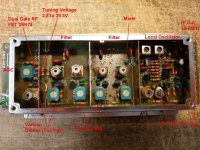
I found a typical front end schematic, and using that started by checking the RF font end assembly, see picture. First section is a standard RF amplifier (3SK74 dual gate Fet) with an input RF tuning coil/varicap. then two filter stage, also tuned by varicap diodes, then possibly the mixer (an other dula gates FET), than the Local oscillator. According to the marking on the module, the 2 Outputs are IF (10.7Mhz), Local oscillator, and there is an AGC dc control voltage + supply.
The tuner display is on, but dim, possibly from age, the tuning pot is working and sending tuning voltage to the front end varicap diodes
Using a scope I confirmed that the LO is alive, and there is IF output. With no input, Tuner tuned at 98Mhz, I fine tuned the LO at 108.7Mhz.
Using a DVM I checked the varicap diode tuning voltage. It changes from 2.8V to 20.5V while tuning the tuner. Seems ok.
Using an RF generator I injected a low signal FM modulated, 100Mhz, 100uV into the RF input, tuned the radio at 100Mhz and checked the IF output, no FM modulation can be seen. I tried to increase a little the RF input, no change. The AGC remains fix at 4.6V, probably Full gain... If the AGC doesn't change it indicates that the tuner is not receiving anything...
So for a start my guess is that the front end RF amplifier transistor is busted, possibly from a static of lightning discharge at the input. Since the LO is working fine and the tuning voltage is changing, I should see a modulated FM IF.
Found a supplier in Europe for the 2SK74 Fet, ordered two.
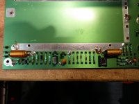
Disassembled the tuner (very funny Naim, all these wires soldered everywhere, solder tuner module, no connectors, except for the cards...
Got the RF module in my hand finally. Waiting for the part to arrive...
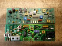
I think I identified most of the tuner section, see pictures. Once the input fet is replaced I'll go further, but I think there is a chance I can save this one...
Feel free to comment and/or give me advice or tips...
The tuner display is on, but dim, possibly from age, the tuning pot is working and sending tuning voltage to the front end varicap diodes
I found a typical front end schematic, and using that started by checking the RF font end assembly, see picture. First section is a standard RF amplifier (3SK74 dual gate Fet) with an input RF tuning coil/varicap. then two filter stage, also tuned by varicap diodes, then possibly the mixer (an other dula gates FET), than the Local oscillator. According to the marking on the module, the 2 Outputs are IF (10.7Mhz), Local oscillator, and there is an AGC dc control voltage + supply.
The tuner display is on, but dim, possibly from age, the tuning pot is working and sending tuning voltage to the front end varicap diodes
Using a scope I confirmed that the LO is alive, and there is IF output. With no input, Tuner tuned at 98Mhz, I fine tuned the LO at 108.7Mhz.
Using a DVM I checked the varicap diode tuning voltage. It changes from 2.8V to 20.5V while tuning the tuner. Seems ok.
Using an RF generator I injected a low signal FM modulated, 100Mhz, 100uV into the RF input, tuned the radio at 100Mhz and checked the IF output, no FM modulation can be seen. I tried to increase a little the RF input, no change. The AGC remains fix at 4.6V, probably Full gain... If the AGC doesn't change it indicates that the tuner is not receiving anything...
So for a start my guess is that the front end RF amplifier transistor is busted, possibly from a static of lightning discharge at the input. Since the LO is working fine and the tuning voltage is changing, I should see a modulated FM IF.
Found a supplier in Europe for the 2SK74 Fet, ordered two.
Disassembled the tuner (very funny Naim, all these wires soldered everywhere, solder tuner module, no connectors, except for the cards...
Got the RF module in my hand finally. Waiting for the part to arrive...
I think I identified most of the tuner section, see pictures. Once the input fet is replaced I'll go further, but I think there is a chance I can save this one...
Feel free to comment and/or give me advice or tips...
Attachments
-
 Front End Module_Top_wt notes.jpg196.3 KB · Views: 422
 -
 Audio Amps_s.jpg189.2 KB · Views: 172
 -
 Supply and Tuning voltage Section_s.jpg728.1 KB · Views: 167
 -
 De-Emphesis_s.jpg145.9 KB · Views: 169
 -
 IF Amp & Discriminator & AGC_s.jpg176 KB · Views: 230
 -
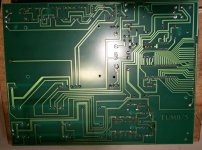 Main PCB_Back_s.jpg160.3 KB · Views: 246
 -
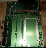 Main PCB_Top_s.jpg147 KB · Views: 324
 -
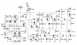
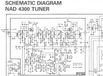 Front end diagram.JPG138.3 KB · Views: 302
Last edited:
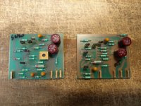
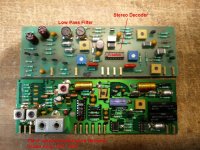
These two PCB are using one chip per board. The HA11225 is doing almost everything: IF Amplifier, Quadrature Detector, Audio amp, AFC and AGC control...
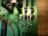
The other board using the TCA4500A is the Stereo decoder, circuit seems to be close to the typical app schematic, see the two coil for the low pass filters...
The other board using the TCA4500A is the Stereo decoder, circuit seems to be close to the typical app schematic, see the two coil for the low pass filters...
Attachments
Received the 3SK74 Fet today, installed it, and fine tuned front end. To get the best result I used an antenna, and while listening to the tuner output, and looking at the AGC voltage, I tuned on a known strong station, Great I hear it! Then I fine tune the front end to get the minimum AGC (Maximum received signal). I was able to reach the sweet spot. Now it tunes correctly to all stations. AGC with no reception tops at 4.75V. With a piece of wire as an antenna, and into the basement, I have now 3.87V with a strong station. Done...
Last edited:

- Status
- This old topic is closed. If you want to reopen this topic, contact a moderator using the "Report Post" button.